
Driving circuit with intelligent induction

A driving circuit, intelligent technology, applied in the direction of electrical components, etc., can solve the problems of reducing product efficiency, increasing the risk of product failure, redundant design, etc., to achieve the effect of isolation, stability and reliability, and low cost

Pending Publication Date: 2020-05-22
UNIVERSELITE
View PDF0 Cites 3 Cited by
  • Summary
  • Abstract
  • Description
  • Claims
  • Application Information

AI Technical Summary

Problems solved by technology

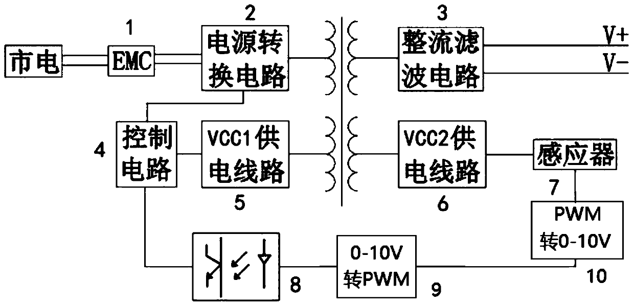
In short, the signal has to be converted between the PWM waveform and 0-10V multiple times, obviously there is redundant design, which reduces the efficiency of the product and increases the risk of bad products

Method used


Image

  • Driving circuit with intelligent induction
  • Driving circuit with intelligent induction
  • Driving circuit with intelligent induction

Examples


Embodiment Construction

[0015] In order to make the technical means of the present invention and the technical effects that can be achieved more clearly and more perfectly disclosed, the following embodiments are provided hereby, and the following detailed descriptions are made in conjunction with the accompanying drawings:

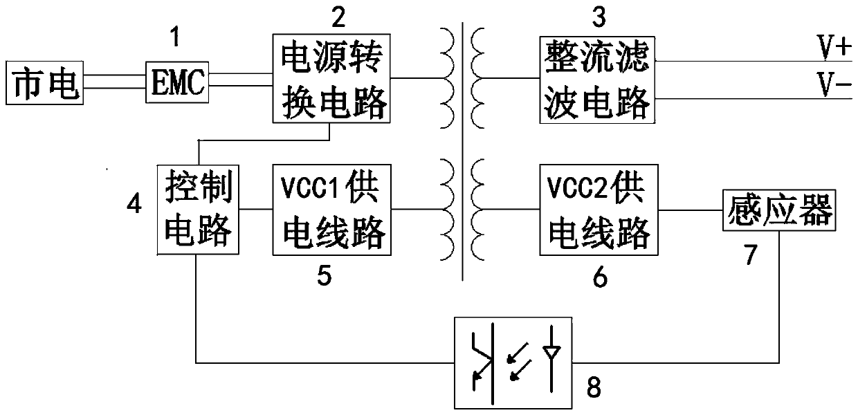
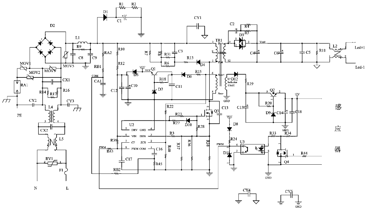
[0016] EMC device 1, power conversion circuit 2, rectification filter circuit 3, VCC1 power supply circuit module 5 (power supply module 1), VCC2 power supply circuit module 6 (power supply module 2) are conventional flyback power supply circuits. The city power is rectified and filtered, and the lamps are controlled to light up after AC-DC conversion. The transformer winding group in the figure is divided into a working winding and a power supply winding. The load provides power output, and the VCC1 and VCC2 power supply lines supply power to the control circuit and the sensor respectively.

[0017] The chip of the control circuit 4 needs to be a power control chip with a PWM d...


PUM


Abstract

The invention provides a driving circuit with an intelligent induction function, and relates to the technical field. The driving circuit comprises an EMC device, a power conversion circuit, a rectification filter circuit, a control circuit connected with the power conversion circuit, a power supply module I for supplying power to the control circuit, a power supply module II for supplying power toan inductor, an optocoupler and the inductor; and the driving circuit further comprises an MOS tube, the grid electrode of the MOS tube is connected with the output pin of the inductor, and the drainelectrode of the MOS tube is connected with the anode of the optocoupler. According to the invention, a PWM signal outputted by a single-chip microcomputer in the inductor is directly used, is isolated by an optical coupler, and is transmitted to the control circuit, the power of the power supply is adjusted, the isolation of the inductor circuit, the input end and the load end is realized at thesame time, and two circuits of converting PWM in the inductor into a 0-10V signal and converting the 0-10V signal in the power supply into a PWM signal are omitted. Stability and reliability of the dimming circuit are facilitated, isolation of the inductor dimming circuit is achieved, and the driving circuit has the advantages of being low in cost and high in reliability.

Description

technical field [0001] The invention relates to a driving circuit for lamps, in particular to a driving circuit with intelligent induction. Background technique [0002] The existing lamps with sensing function are basically designed separately from the driver and the sensor, mainly converting the signal sensed by the sensor into a 0-10V signal, and then transmitting the 0-10V signal to the driver to control the driver output to adjust the brightness of the lamp. This solution has redundant designs, wastes resources, and has low work efficiency; meanwhile, it cannot well meet the needs of supporting production of lamps. Existing sensors control the output through a single-chip microcomputer. The output of the single-chip microcomputer is a PWM waveform, so it is necessary to convert the PWM waveform into a 0-10V signal. After the driver receives the 0-10V signal, it needs to convert the 0-10V signal into The PWM waveform is then transmitted to the power control chip with P...

Claims


Application Information

Patent Timeline
Patent Type & Authority Applications(China)
IPC IPC(8): H05B45/325
CPCH05B45/325H05B45/385H05B47/115
Inventor 许剑钢马位赣
Owner UNIVERSELITE
Learn More