Eureka AIR delivers breakthrough ideas for toughest innovation challenges, trusted by R&D personnel around the world.

Microwave photon waveform generation device and method based on cyclic frequency shift

A technology of microwave photons and generating devices, which is applied in the field of microwave photons, can solve problems such as the influence of waveform accuracy and the inability to completely suppress the second-order harmonic components, and achieve the effect of pure spectral components and suppression of second-order harmonic components

Active Publication Date: 2020-05-22
苏州枫桥光电科技有限公司
View PDF6 Cites 3 Cited by
  • Summary
  • Abstract
  • Description
  • Claims
  • Application Information

AI Technical Summary

Problems solved by technology

As far as the generation of triangular waves is concerned, the above methods are to obtain the first-order and third-order harmonic components with a frequency ratio of 1:3 and an amplitude ratio of 1:9 by controlling the modulation coefficient and bias voltage. These two harmonics are exactly It is equal to the first two Fourier series components of the triangular wave, but it cannot completely suppress the second-order harmonic component, which will have a certain impact on the accuracy of the waveform

Method used


Image

  • Microwave photon waveform generation device and method based on cyclic frequency shift
  • Microwave photon waveform generation device and method based on cyclic frequency shift
  • Microwave photon waveform generation device and method based on cyclic frequency shift

Examples


Embodiment 1

[0087] In the case of the same frequency shift, different filtering curves of the band-pass filter correspond to different microwave waveforms.

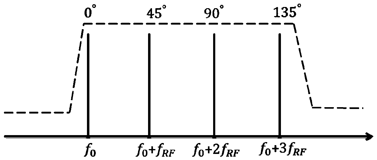
[0088] Optical carrier wavelength λ=1550nm, frequency shift f s =20GHz, loop delay τ=10 -8 s, the optical carrier power is 0dBm, when the filtering curve of the filter is flat-top type, the generated rectangular wave is as follows Figure 6 As shown, the period of the obtained rectangular wave is 50ps.

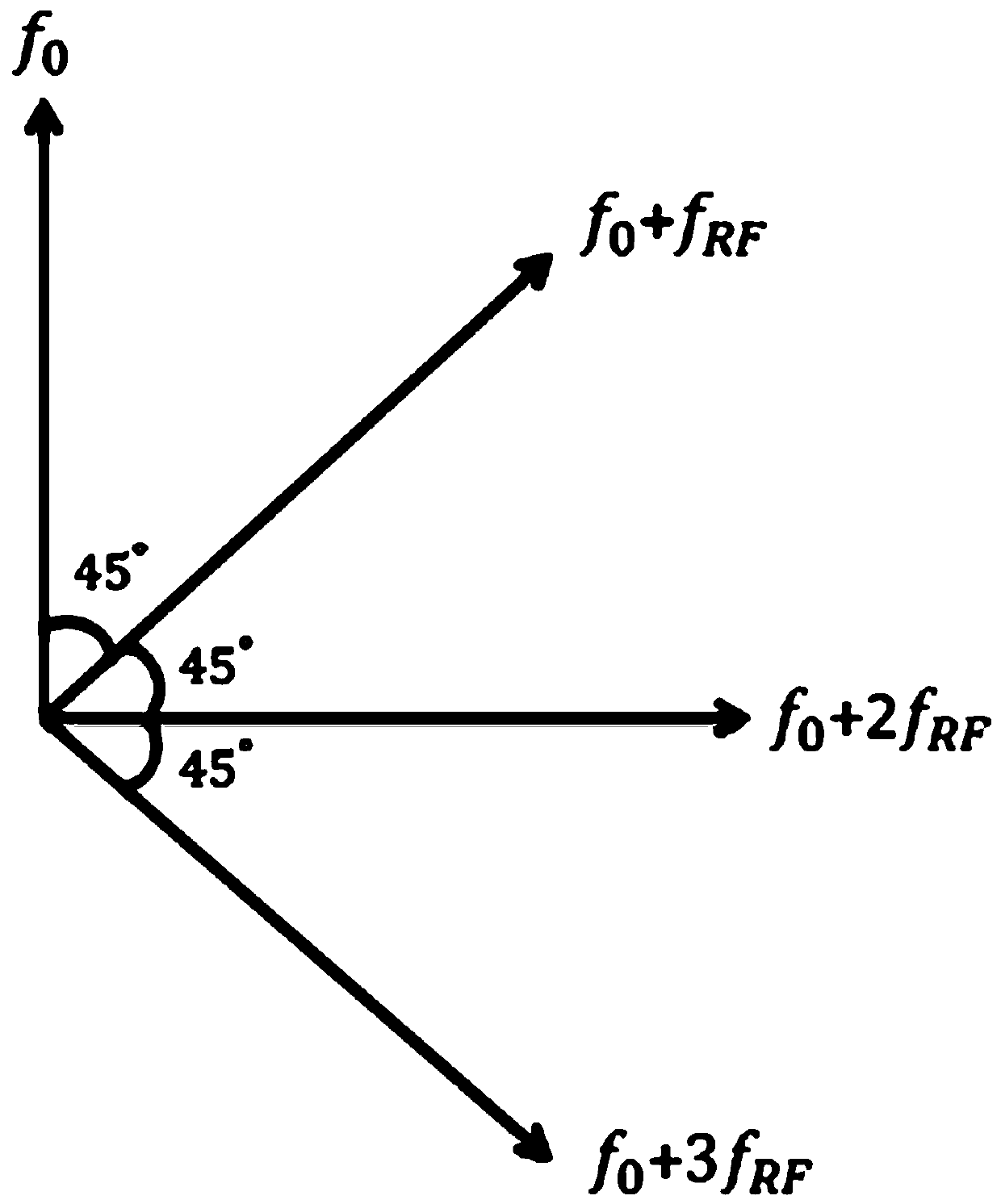
[0089] When the filtering curve of the filter is adjusted to be trapezoidal, other parameters remain unchanged, and a 90-degree electric phase shifter is added behind the photodetector to generate a triangular wave such as Figure 7 shown.

[0090] To sum up, in the case of the same frequency shift amount, the device and method can be used to generate microwave waveforms with tunable waveforms.

Embodiment 2

[0092] In the case of the same waveform, different frequency shift amounts correspond to triangular waves of different frequencies.

[0093] In Example 1, the amount of frequency shift is 20GHz, adjust the amount of frequency shift to 5GHz, the frequency of the obtained triangular wave is 5GHz, and the time domain waveform is as follows Figure 8 shown. Figure 9 The spectrum diagram corresponding to the 5GHz triangular wave can be seen from the spectrum diagram, which only contains the first-order 5GHz harmonic and the third-order 15GHz harmonic. The power ratio between the two is about 20dB, which is close to the ideal power ratio of 19.085dB.

[0094] To sum up, under the condition that the waveform remains unchanged, the device and method can be used to generate microwave waveforms with adjustable frequency.


PUM


Abstract

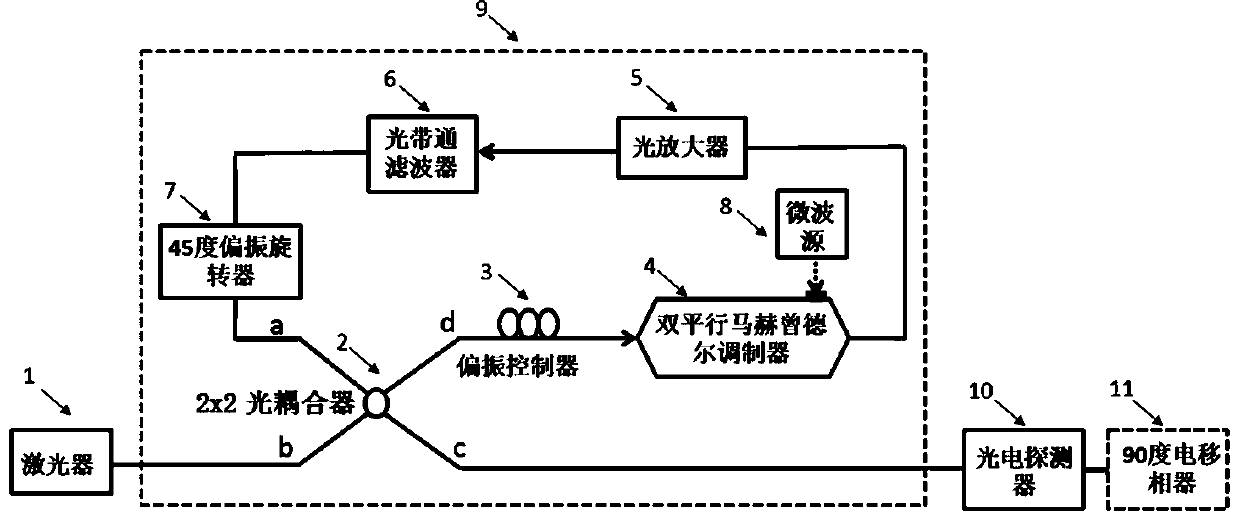
The invention relates to a microwave photon waveform generation device based on cyclic frequency shift. The device comprises a laser, a cyclic frequency shift module, a photoelectric detector and a 90-degree electric phase shifter; the laser is optically connected with a light input port b of the cyclic frequency shift module, a light input port of the photoelectric detector is optically connectedwith a light output port c of the cyclic frequency shift module, and the 90-degree electric phase shifter is electrically connected with an output port of the photoelectric detector. The invention provides a microwave photon waveform generation device and a microwave photon waveform generation method based on cyclic frequency shift, which can realize waveform generation of a broadband tunable microwave signal of which a second-order harmonic component is completely suppressed.

Description

technical field [0001] The invention relates to the field of microwave photon technology, in particular to a microwave photon waveform generation device and a microwave photon waveform generation method based on cyclic frequency shifting. Background technique [0002] In recent years, arbitrary waveform generation technology based on microwave photonics has become a research hotspot because of its wide application in radar, measurement, wireless communication and microwave signal processing, among which rectangular wave and triangular wave are used in optical frequency conversion, pulse compression and signal replication etc. play an important role. The traditional arbitrary waveform generation technology based on electronics is difficult to generate high-frequency arbitrary waveform signals due to the limitation of sampling rate; while the method based on microwave photonics can effectively break through the "electronic bottleneck" with large bandwidth and low transmission ...

Claims


Application Information

Patent Timeline
IPC IPC(8): H04B10/50H04B10/516
CPCH04B10/505H04B10/5053H04B10/5165
Inventor 杜明刘永慕飒米张少先李侠
Owner 苏州枫桥光电科技有限公司
Why Eureka
Eureka Blog
Learn More