Video monitoring equipment cascading method and device
A video surveillance, equipment-level technology, applied in the field of video surveillance equipment cascading methods and devices, can solve the problems of limited monitoring area and reduced video stream transmission performance, and achieve the effect of expanding the monitoring area and improving transmission performance.
- Summary
- Abstract
- Description
- Claims
- Application Information
AI Technical Summary
Problems solved by technology
Method used
Image


Examples
Embodiment 1
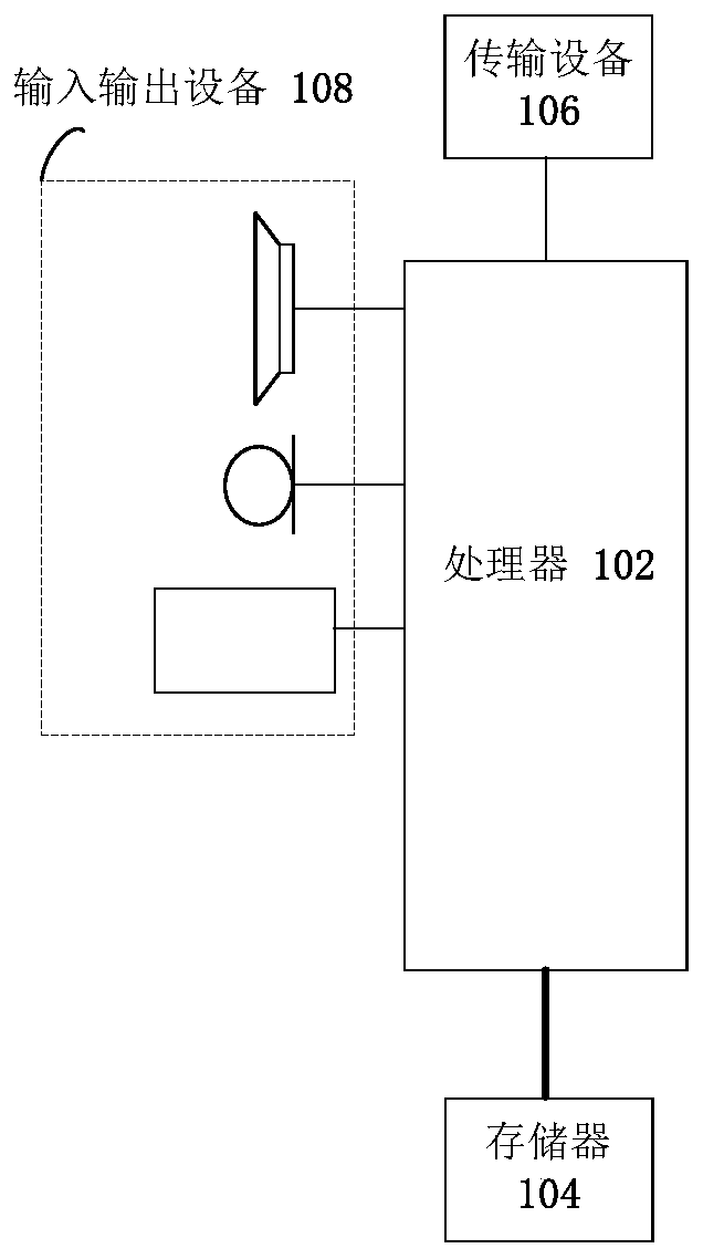
[0068] The method embodiment provided in Embodiment 1 of the present application may be executed in a mobile terminal, a computer terminal, or a similar computing device. Taking running on a mobile terminal as an example, figure 1 It is a block diagram of the hardware structure of a mobile terminal of a video surveillance device cascading method according to an embodiment of the present invention, as figure 1 As shown, the mobile terminal 10 may include one or more ( figure 1 Only one is shown in the figure) a processor 102 (the processor 102 may include but not limited to a processing device such as a microprocessor MCU or a programmable logic device FPGA) and a memory 104 for storing data. Optionally, the above-mentioned mobile terminal also A transmission device 106 for communication functions as well as input and output devices 108 may be included. Those of ordinary skill in the art can understand that, figure 1 The shown structure is only for illustration, and does not...
Embodiment 2
[0087] According to another embodiment of the present invention, a video surveillance networking method is also provided, image 3 It is the flow of the video surveillance networking method according to the embodiment of the present invention Figure II ,like image 3 shown, including:
[0088] Step S302, the IPC establishes a network connection with the NVR;
[0089] Step S304, the IPC receives a notification message sent by the NVR, wherein the notification message is the hotspot information of the wireless device acquired by the NVR when a wireless device is detected, wherein the The wireless device is connected to the local area network;
[0090] Step S306, the IPC establishes a cascade connection with the wireless device through the hotspot information of the wireless device.
[0091] Through the above steps S302 to S306, it is possible to solve the problem in the related art that the transmission performance of each cascaded level of video code stream is degraded and...
Embodiment 3
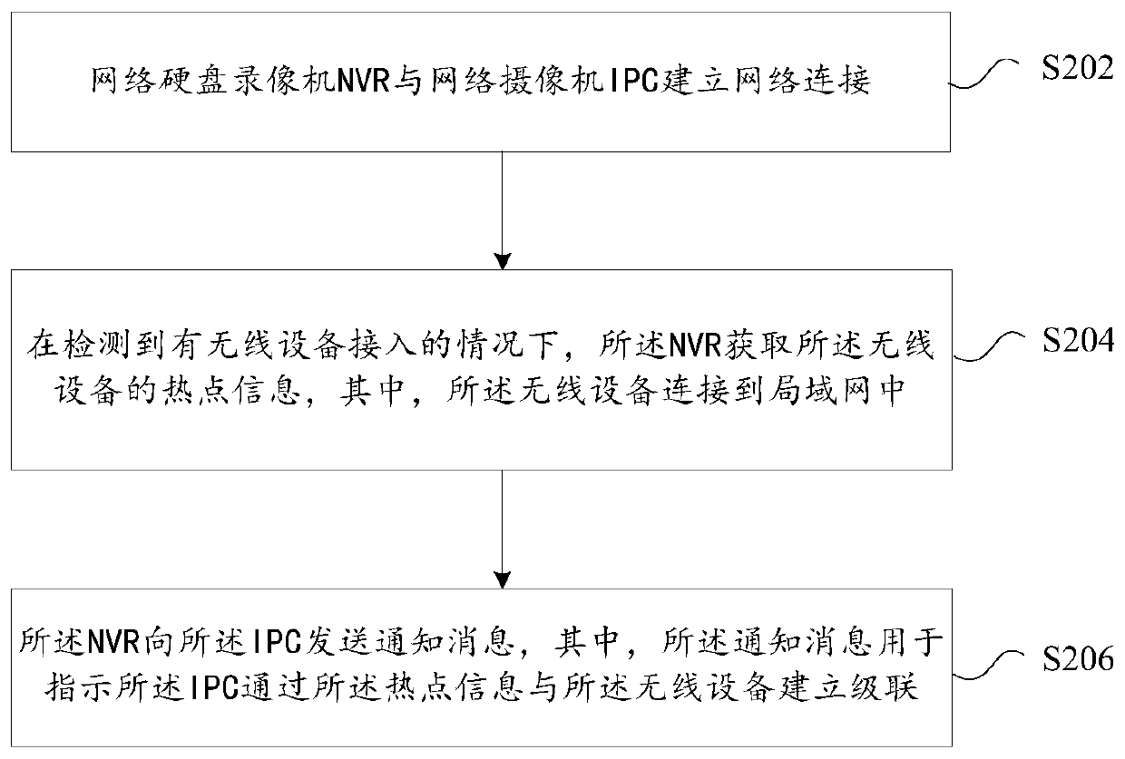
[0117] According to another embodiment of the present invention, a cascading device for video monitoring equipment is also provided, which is applied to a network hard disk video recorder NVR, Image 6 is the frame of the cascaded device for video surveillance equipment according to the embodiment of the present invention Figure 1 ,like Image 6 shown, including:
[0118] The first connection establishment module 62 is used to establish a network connection with the network camera IPC;
[0119] An obtaining module 64, configured to obtain hotspot information of the wireless device when it is detected that a wireless device is connected, wherein the wireless device is connected to a local area network;
[0120] The sending module 66 is configured to send a notification message to the IPC, where the notification message is used to instruct the IPC to establish a concatenation with the wireless device through the hotspot information of the wireless device.
[0121] Optionally...
PUM
 Abstract
Description
Claims
Application Information
 - R&D
- Intellectual Property
- Life Sciences
- Materials
- Tech Scout
- Unparalleled Data Quality
- Higher Quality Content
- 60% Fewer Hallucinations
Browse by: Latest US Patents, China's latest patents, Technical Efficacy Thesaurus, Application Domain, Technology Topic, Popular Technical Reports.
© 2025 PatSnap. All rights reserved.Legal|Privacy policy|Modern Slavery Act Transparency Statement|Sitemap|About US| Contact US: help@patsnap.com