
A high-efficiency anode tube for ion source

An anode tube and ion source technology, applied in the field of electron sources, can solve problems such as uneven distribution of reactive gases, low adsorption efficiency of electronic dust, and reduced working efficiency of ion sources, so as to expand adsorption points, save materials, and avoid overall replacement Effect

Active Publication Date: 2022-08-09
江苏派莱特光电科技有限公司
View PDF6 Cites 0 Cited by
  • Summary
  • Abstract
  • Description
  • Claims
  • Application Information

AI Technical Summary

Problems solved by technology

However, there is no ventilation hole on the existing anode tube, and the reaction gas enters directly from one port of the anode tube, resulting in uneven distribution of the reaction gas and poor ionization; the anode tube is integrally formed, so that the anode tube part needs to When replacing, it must be replaced as a whole, resulting in a large waste; the adsorption efficiency of electronic dust generated during the cathode ionization process of the ion source is low, and the effect is poor, resulting in a greatly reduced working efficiency of the ion source, which in turn affects the entire coating process.

Method used


Image

  • A high-efficiency anode tube for ion source
  • A high-efficiency anode tube for ion source
  • A high-efficiency anode tube for ion source

Examples


Embodiment Construction

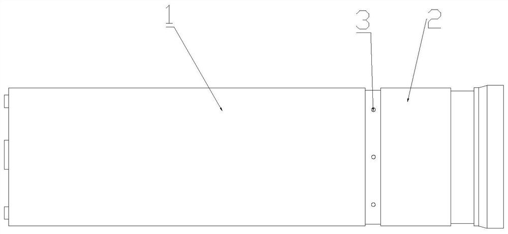
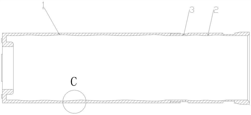
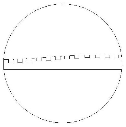
[0015] As shown in the manual Figure 1 to Figure 3 The shown high-efficiency anode tube for ion source includes a first anode tube 1 and a second anode tube 2, the first anode tube 1 and the second anode tube 2 are sleeved together with each other, and the first anode tube 1 and the second anode tube The inner wall of the anode tube 2 is wave-shaped, and the inner walls of the first anode tube 1 and the second anode tube 2 are uneven, and the unevenness can be obtained by sandblasting, chemical treatment or mechanical treatment. One end is provided with a vent hole 3 along the circumference, and the inner diameter of the vent hole 3 is small on the outside and large on the inside.

[0016] The first anode tube 1 and the second anode tube 2 are screwed and sleeved together by means of threaded connection, and the connection is detachable. Which part is damaged and which part is replaced, so as to avoid overall replacement.

[0017] The first anode tube 1 and the second anode ...


PUM


Abstract

The invention discloses a high-efficiency anode tube for an ion source, comprising a first anode tube and a second anode tube, the first anode tube and the second anode tube are sleeved together, and the inner walls of the first anode tube and the second anode tube are It is wave-shaped, and the inner walls of the first anode tube and the second anode tube are rough and uneven, and one end of the second anode tube is provided with a ventilation hole along the circumference, and the inner diameter of the ventilation hole is small outside and large inside. The invention adopts the setting of double anode tubes, which can be detachably connected to avoid overall replacement; the second anode tube is evenly provided with ventilation holes along the circumference, and the reaction gas enters evenly, so that the reaction gas is evenly distributed; the first anode tube and the second anode tube The inner wall of the tube is wavy and the inner wall is uneven, which improves the adsorption efficiency of electronic dust.

Description

technical field [0001] The invention belongs to the field of electron sources, and in particular relates to a high-efficiency anode tube for ion sources. Background technique [0002] Ion beam thin film deposition and ion beam material modification techniques are an important branch of materials science. At present, there are many types of ion sources, but the basic working principle is: first, the cathode generates plasma in the inner cavity of the ion source, and then the ions are extracted from the plasma cavity by two or three layers of anode grids. The ion has strong directivity and concentrated ion energy bandwidth, which can be widely used in vacuum coating. [0003] In the ion source, the anode tube is an important part. The reaction gas introduced into the anode tube generates plasma under the action of the cathode, and then the plasma is extracted through the screen grid and the acceleration grid. However, the existing anode tube does not have ventilation holes, ...

Claims


Application Information

Patent Timeline
Patent Type & Authority Patents(China)
IPC IPC(8): H01J37/32
CPCH01J37/32605H01J37/32541
Inventor 安建昊唐欢欢
Owner 江苏派莱特光电科技有限公司
Learn More