Eureka AIR delivers breakthrough ideas for toughest innovation challenges, trusted by R&D personnel around the world.

Configuration item testing method for hydraulic control software

A technology for controlling software and testing methods, applied in software testing/debugging, error detection/correction, instruments, etc., to solve problems such as uncontrollable testing progress, uncontrolled testing progress, and difficulty in fault location, to meet the requirements of complete testing. requirements for test integrity and adequacy, assurance of test integrity and adequacy, and the effect of easy fault location

Active Publication Date: 2020-05-19
XIAN AIRCRAFT DESIGN INST OF AVIATION IND OF CHINA
View PDF7 Cites 0 Cited by
  • Summary
  • Abstract
  • Description
  • Claims
  • Application Information

AI Technical Summary

Problems solved by technology

[0003] Since the test verification environment is generally built in the initial stage of system development, its main function is to support the later system function-level verification, mainly composed of hardware equipment, which is affected by the change maintenance cycle, and software testing is at the front end of system function verification during the system development process, so , the test verification environment is often partially different from the current software test requirement environment, and cannot fully support the fault injection required for testing. The configuration item test often needs to be modified according to the test verification environment state (referring to the physical environment, such as including emergency equipment) Test cases, it is difficult to ensure that all normal and abnormal test cases can be effectively executed, resulting in the failure to guarantee the integrity and adequacy of the test
Usually, the test verification environment can only be manually performed by the operator for test operation and result comparison and analysis. Affected by the complexity of the test environment, it is difficult to locate faults and the test progress is not controlled. At the same time, the complex hardware environment makes it difficult to locate faults when the test is abnormal. Large, resulting in uncontrollable test progress
In addition, due to the strong coupling between the embedded software and the system in which it is located, and the poor versatility of the software, there is no tool on the market that can support the automation of embedded software configuration item testing.

Method used


Image

  • Configuration item testing method for hydraulic control software
  • Configuration item testing method for hydraulic control software
  • Configuration item testing method for hydraulic control software

Examples


Embodiment Construction

[0035] In order to make the purpose, technical solution and advantages of the present invention more clear, the embodiments of the present invention will be described in detail below in conjunction with the accompanying drawings. It should be noted that, in the case of no conflict, the embodiments in the present application and the features in the embodiments can be combined arbitrarily with each other.

[0036] The following specific embodiments provided by the present invention can be combined with each other, and the same or similar concepts or processes may not be repeated in some embodiments.

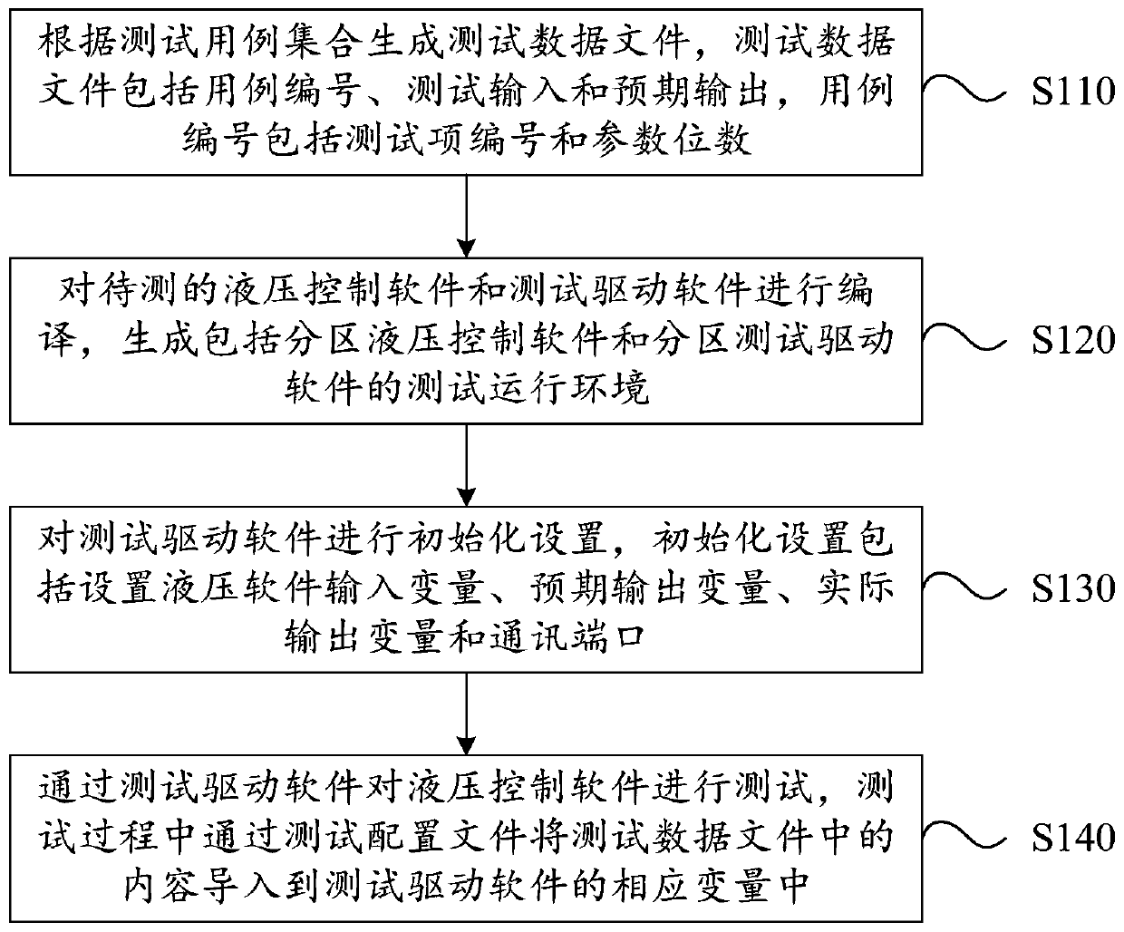
[0037] figure 1 It is a flow chart of a method for testing configuration items of hydraulic control software provided by an embodiment of the present invention. The configuration item testing method of the hydraulic control software provided in this embodiment may include the following steps:

[0038] S110, generating a test data file according to the test case set, the test data...


PUM


Abstract

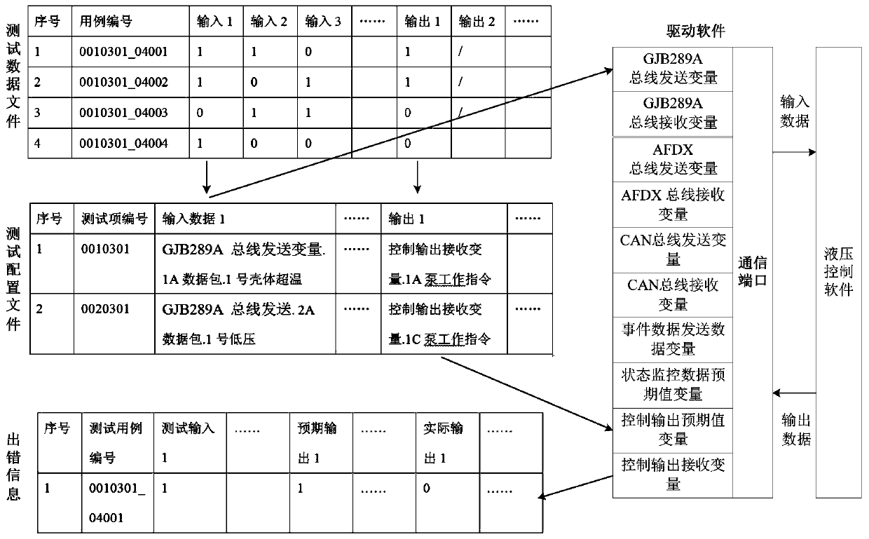
The embodiment of the invention discloses a configuration item test method for hydraulic control software, which comprises the following steps: generating a test data file according to a test case set, the test data file comprising a case number, a test input and an expected output; compiling the to-be-tested hydraulic control software and the to-be-tested test driving software to generate a testrunning environment comprising partition hydraulic control software and partition test driving software; performing initialization setting on the test driving software, wherein the initialization setting comprises setting a hydraulic software input variable, an expected output variable, an actual output variable and a communication port; and testing the hydraulic control software through the testdriving software, and importing test data in the test data file into corresponding variables of the test driving software through the test configuration file in the test process. According to the embodiment of the invention, the test data is automatically input, the output data is automatically compared and analyzed, errors possibly caused by manual operation are avoided, the result is accurate, and the execution efficiency is high.

Description

technical field [0001] This application relates to but is not limited to the technical field of airborne software testing, especially a method for testing configuration items of hydraulic control software. Background technique [0002] Hydraulic control software is a typical real-time embedded software. It has the characteristics of many cross-linking devices, complex communication types, large amount of interface data, and simple control logic. Its configuration items are often tested with the help of system test verification environment. [0003] Since the test verification environment is generally built in the initial stage of system development, its main function is to support the later system function-level verification, mainly composed of hardware equipment, which is affected by the change maintenance cycle, and software testing is at the front end of system function verification during the system development process, so , the test verification environment is often par...

Claims


Application Information

Patent Timeline
Patent Type & Authority Applications(China)
IPC IPC(8): G06F11/36
CPCG06F11/3684G06F11/3688G06F11/3692Y02P90/02
Inventor 成红芳刘佳李国栋赵博锋
Owner XIAN AIRCRAFT DESIGN INST OF AVIATION IND OF CHINA
Why Eureka
Eureka Blog
Learn More