
Novel current transformer and implementation method

A current transformer and a new type of technology, applied in the field of transformers, can solve the problems of reduced reliability, matching, and narrow application scope, and achieve the effects of eliminating manufacturing errors, increasing applicable occasions, and facilitating safe maintenance.

Active Publication Date: 2020-05-19
付涛阳
View PDF9 Cites 2 Cited by
  • Summary
  • Abstract
  • Description
  • Claims
  • Application Information

AI Technical Summary

Problems solved by technology

The chips and electronic components in the integrating circuit also have the problems mentioned above, which reduces the accuracy of measurement.
[0006] 2. The scope of application is narrow; the output of the low-voltage end of the existing electronic current transformer is 4V small voltage analog signal or digital signal
Unless it is a newly built purely digital power station, it cannot be used with instruments that need to input 5A analog current (many of them are pointer instruments), nor can it drive relay devices
For old-fashioned power distribution cabinets and substations that are in use and need to be repaired or modified, this electronic current transformer that can only output 4V small voltage analog signals or digital signals cannot be matched with the original instruments and devices, which greatly limits Its scope of application
[0007] 3. Power supply is difficult; the high-voltage end acquisition head of the electronic current transformer usually has an electronic circuit, which needs to be supplied with power to work
Therefore, the circuit control of the whole system is also more complicated, the total cost of the product becomes higher, and the reliability will decrease

Method used


Image

  • Novel current transformer and implementation method
  • Novel current transformer and implementation method
  • Novel current transformer and implementation method

Examples


Embodiment Construction

[0039] The novel current transformer and implementation method of the present invention will be described in detail below with reference to the accompanying drawings and embodiments.

[0040] The novel current transformer of the present invention includes a high-voltage terminal module and a low-voltage terminal module; the high-voltage terminal module and the low-voltage terminal module are connected through optical fibers; and also includes a hollow coil and a long-distance wireless power supply device.

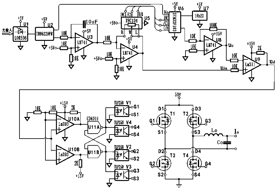
[0041] Such as figure 1 As shown, the high-voltage terminal module includes an impedance matching circuit module (composed of R, L, C1, and C2), a high-voltage terminal intelligent gain control circuit module (Ug1, Ug2), a digital modulation circuit module (Ug5), and an electro-optical conversion circuit module. (Ug6), high-voltage end MCU (Ug3) and high-voltage end temperature sensor (Ug4). The air-core coil is connected to the input of the impedance matching circuit modu...


PUM


Abstract

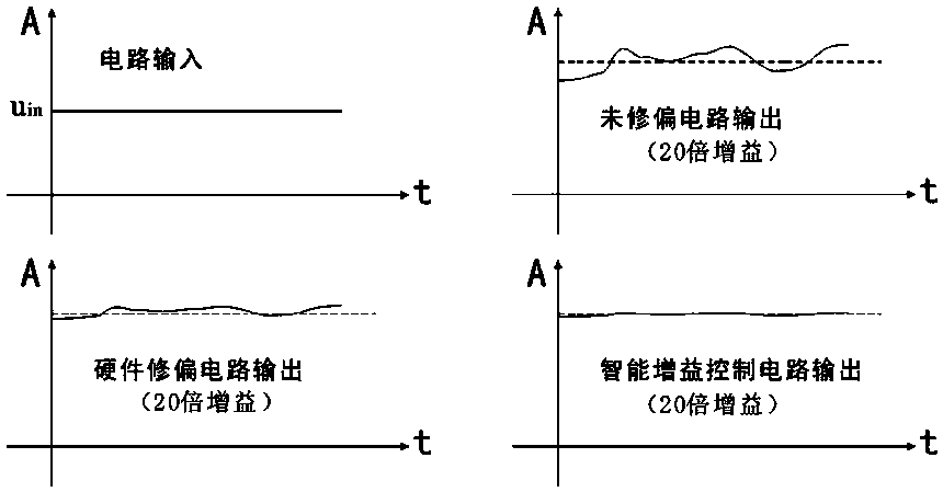
The invention relates to a novel current transformer and an implementation method and belongs to the field of the transformer. The transformer comprises a high-voltage end module and a low-voltage endmodule. The transformer is characterized by further comprising a hollow coil and a long-distance wireless power supply device, wherein one end of an optical fiber is connected with a photoelectric conversion circuit module, and the other end is connected with the photoelectric conversion circuit module. By adopting an intelligent gain control circuit module, a manufacturing error of the hollow coil, parameter deviation of electronic components and the temperature drift of an electronic circuit caused by temperature and humidity changes are eliminated, and measurement precision is high. Through a pulse width modulation circuit module, an inverter drive circuit module, a power inverter bridge and a low-pass filter, a current transformer can output the same current value and power as a secondary end of a traditional electromagnetic current transformer, and is matched with various existing instruments and power distribution cabinets. A long-distance wireless power supply device solves a power supply problem of a high-voltage end acquisition head of the hollow coil type current transformer, has no power supply dead angle or measurement dead zone, and is convenient to maintain safely, good in stability and long in service life.

Description

technical field [0001] The invention belongs to the field of transformers, in particular to a novel current transformer and a realization method. Background technique [0002] Current transformer is a device used to convert high voltage and high current into low voltage and small current for measurement and use according to a certain ratio, including traditional electromagnetic current transformer and electronic current transformer, electronic The type current transformer mainly uses optical fiber to transmit the electrical parameters collected at the high-voltage end to the low-voltage end, and the low-voltage end is converted into an electrical signal by optical-electrical conversion for further processing. Electronic current transformers can be divided into three types in principle: optical current transformers, air-core coil current transformers and iron-core coil low-power current transformers. [0003] The sensing head part of the optical current transformer generally...

Claims


Application Information

Patent Timeline
IPC IPC(8): G01R15/18G01R19/00
CPCG01R15/181G01R19/0092
Inventor 付涛阳
Owner 付涛阳
Learn More