A locking mechanism and padlock

A technology of locking mechanism and driving mechanism, which is applied in padlocks, building locks, building structures, etc., and can solve problems such as slider instability and false unlocking

Active Publication Date: 2021-04-23
ZHUHAI UNITECH POWER TECH CO LTD
View PDF5 Cites 0 Cited by
  • Summary
  • Abstract
  • Description
  • Claims
  • Application Information

AI Technical Summary

Problems solved by technology

[0003] The embodiment of the present application provides a locking mechanism and a padlock to solve the problem of unintentional unlocking caused by the instability of the slider

Method used


Image

  • A locking mechanism and padlock
  • A locking mechanism and padlock
  • A locking mechanism and padlock

Examples


Embodiment

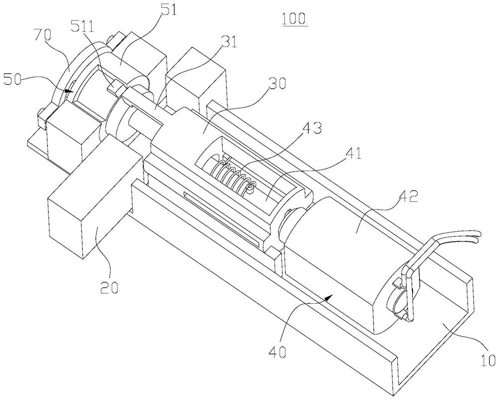
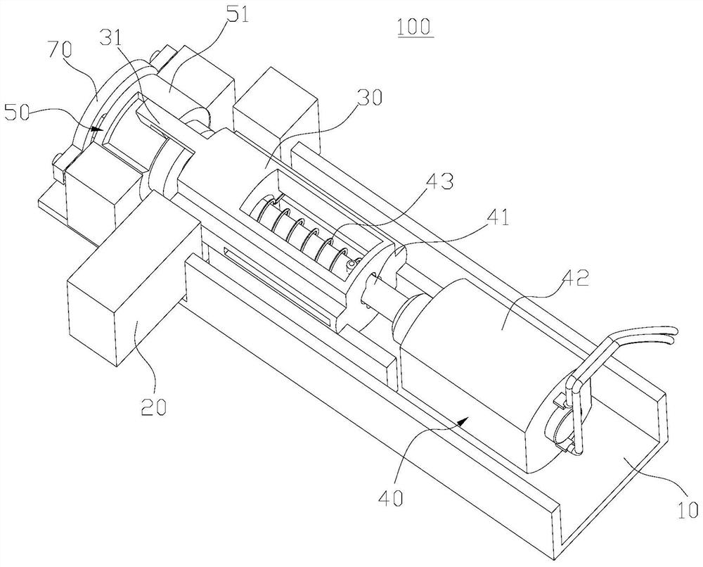
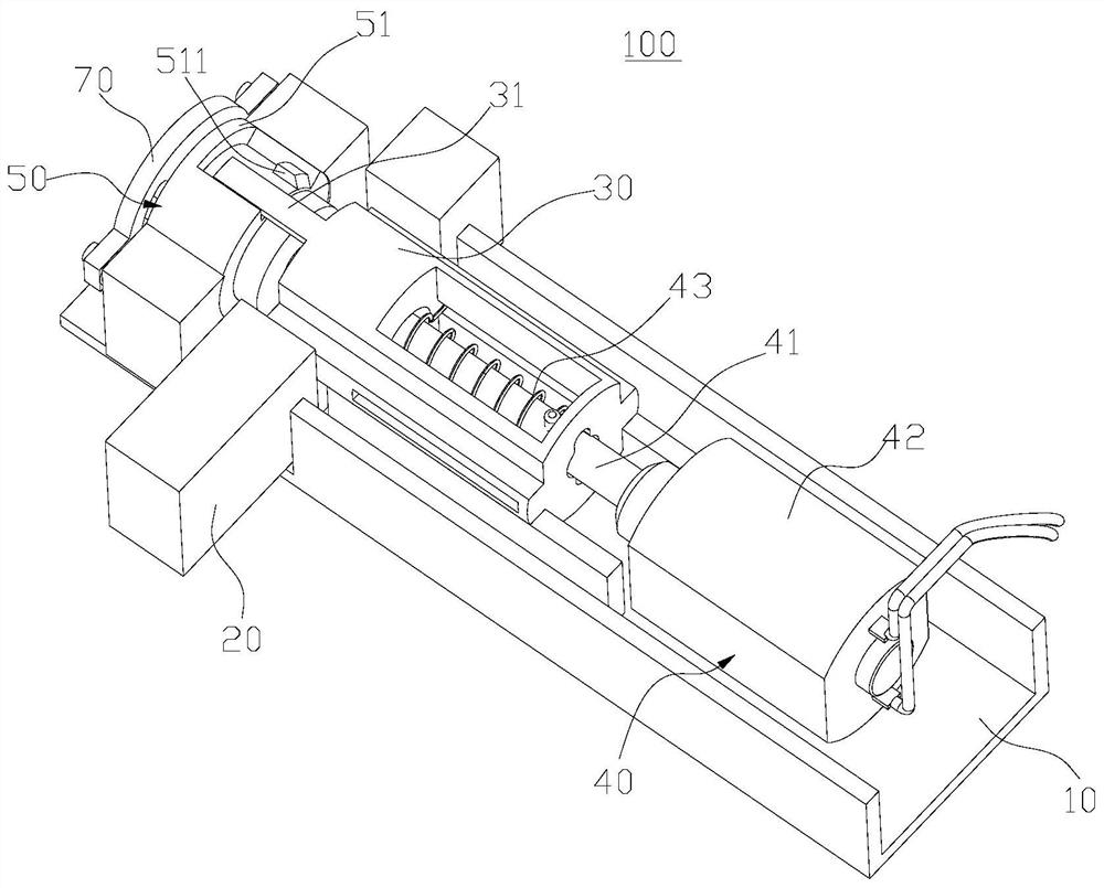
[0068] The present application provides a locking mechanism 100, which can effectively prevent the sliding block 30 from being unsteadily unlocked by mistake. Combine the following Figure 1-Figure 6 The structure of the locking mechanism 100 will be described in detail.

[0069] like Figure 1-Figure 4 As shown, the locking mechanism 100 includes a lock body 10 , a lock pin 20 , a slider 30 , a driving mechanism 40 and a locking device 50 .

[0070] The lock pin 20 is movably disposed on the lock body 10 . The slider 30 is movably disposed on the lock body 10 , and the slider 30 has a first position for locking the lock pin 20 and a second position for unlocking the lock pin 20 . The driving mechanism 40 is used to drive the slider 30 to move between the first position and the second position. The locking device 50 is used to releasably lock the slider 30 in the first position.

[0071] When the slider 30 is located at the first position and the lock pin 20 is locked, th...


PUM


Abstract

The application provides a locking mechanism and a padlock, belonging to the field of locks. Wherein, the locking mechanism includes a lock body, a lock pin, a slide block, a driving mechanism and a locking mechanism. The lock pin is movably arranged on the lock body. The slider is movably arranged on the lock body, and the slider has a first position for locking the lock pin and a second position for unlocking the lock pin. The driving mechanism is used to drive the slider to move between the first position and the second position. A locking mechanism is used to releasably lock the slider in the first position. When the slider is at the first position and the lock pin is locked, the slider can be locked by the locking mechanism, so that the slider has good stability at the first position, effectively avoiding the situation of accidentally unlocking. When the lock needs to be unlocked, the sliding block can be released by the locking mechanism. After the driving mechanism drives the sliding block to move from the first position to the second position, the lock pin is unlocked, and the lock pin can move relative to the lock body to realize unlocking.

Description

technical field [0001] The present application relates to the field of locks, in particular to a locking mechanism and a padlock. Background technique [0002] At present, most padlocks use a slider to lock the pin to lock the U-shaped shackle of the padlock, but the slider is prone to instability, resulting in accidental unlocking. Contents of the invention [0003] Embodiments of the present application provide a locking mechanism and a padlock, so as to solve the problem of unintentional unlocking caused by the instability of the slider. [0004] In the first aspect, the embodiment of the present application provides a locking mechanism, including a lock body, a lock pin, a slider, a driving mechanism, and a locking device; [0005] The lock pin is movably arranged on the lock body; [0006] The slider is movably arranged on the lock body, and the slider has a first position for locking the lock pin and a second position for unlocking the lock pin; [0007] The drivi...

Claims


Application Information

Patent Timeline
Patent Type & Authority Patents(China)
IPC IPC(8): E05B67/22E05B67/38E05B47/00E05B15/00E05B15/04
CPCE05B15/00E05B15/04E05B47/0012E05B47/0603E05B67/22E05B67/38E05B2015/0406E05B2047/0013
Inventor 李启平何海雄许海丰李保福
Owner ZHUHAI UNITECH POWER TECH CO LTD
Why Eureka
Try Eureka