Valve polishing device convenient to adjust for sewage treatment

A polishing device and sewage treatment technology, which is applied in the direction of grinding drive device, grinding/polishing equipment, surface polishing machine tool, etc., can solve the problems of wasting manpower and low efficiency, and achieve the effect of improving processing quality

Active Publication Date: 2020-05-19
CNOOC DONGYING PETROCHEMICAL CO LTD
View PDF3 Cites 5 Cited by
  • Summary
  • Abstract
  • Description
  • Claims
  • Application Information

AI Technical Summary

Problems solved by technology

In the process of sewage treatment, it is necessary to use valves to control the sewage pipes. During the processing of the valves, the surface needs to be polished for subsequent painting; in the prior art, when the surface of the valve is polished, the angle of the valve needs to be constantly adjusted to The entire surface can be effectively polished; this operation not only wastes a lot of manpower, but also has low efficiency; therefore, it is necessary to improve the existing technology and provide an easy-to-adjust valve polishing device for sewage treatment to improve Actual Processing Efficiency

Method used


Image

  • Valve polishing device convenient to adjust for sewage treatment
  • Valve polishing device convenient to adjust for sewage treatment
  • Valve polishing device convenient to adjust for sewage treatment

Examples


Embodiment 1

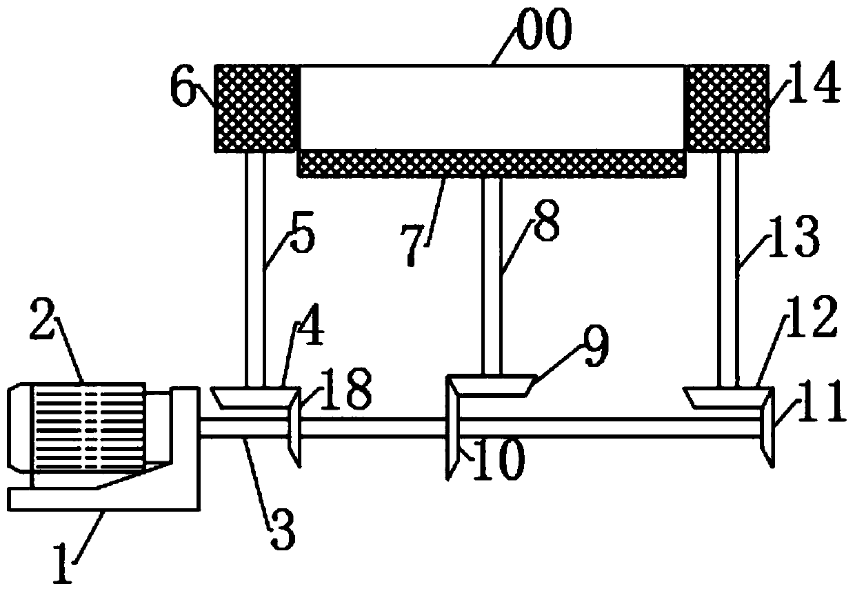
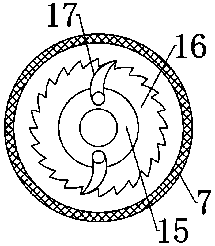
[0017] see Figure 1-3 , a valve polishing device for sewage treatment that is easy to adjust, including a workbench 7, on which a valve 00 to be polished is placed, the workbench 7 is connected with a power mechanism that can make it rotate, and a polishing wheel-6 is arranged on both sides and polishing wheel 2 14; polishing wheel 1 6 and polishing wheel 2 14 are connected to the power mechanism and are located at the edges of both sides of the valve 00.

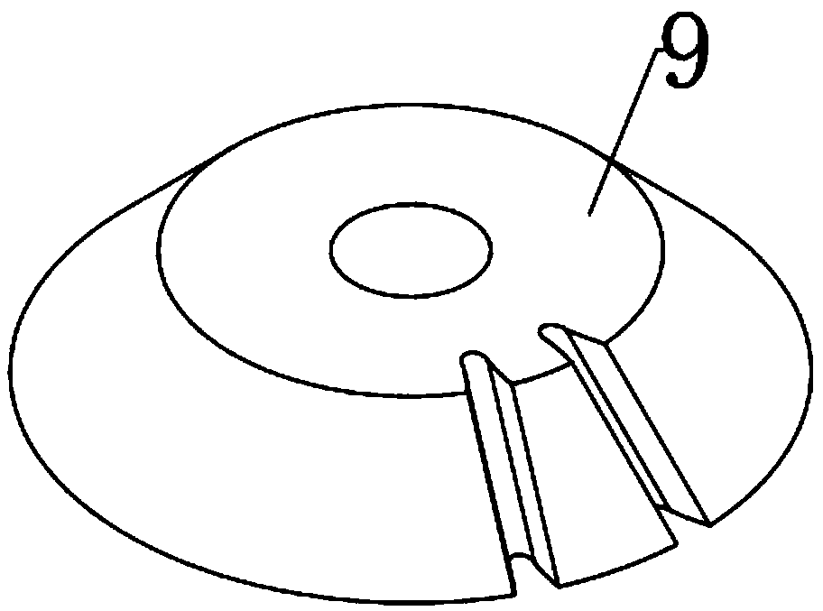
[0018] The specific structure of the power mechanism is not limited, preferably, in the present embodiment, the power mechanism includes a base 1, a motor 2 is arranged on the base 1, and the motor 2 is connected to the drive shaft 3; Helical gear 3 18, helical gear 1 10 and helical gear 2 11 are arranged at intervals, and an intermittent wheel 9 meshing with it is arranged above the helical gear 10, and the intermittent wheel 9 is connected with the rotating shaft 8, and the other end of the rotating shaft 8 It is fixedl...

Embodiment 2

[0025] In embodiment 1, the wall surface of polishing wheel 1 6 and polishing wheel 2 14 is the working contact surface, and greater wear will occur during the working process. If things go on like this, it will affect the polishing precision of valve 00; therefore, this embodiment is in Improvements are made on the basis of Example 1. The improvements are: under the premise of ensuring the machining accuracy, the walls of polishing wheel one 6 and polishing wheel two 14 are plated with a wear-resistant coating to slow down the process of polishing wheel one 6 and polishing wheel two. The wear rate of 214 prolongs the service life of the whole device.


PUM


Abstract

The invention discloses a valve polishing device convenient to adjust for sewage treatment. The valve polishing device comprises a workbench, a to-be-polished valve is placed on the workbench, and a first polishing wheel and a second polishing wheel for machining the valve are arranged at the edges of the two sides of the valve; and the workbench is connected with a power mechanism capable of making the workbench rotate, and the first polishing wheel and the second polishing wheel are connected with the power mechanism. According to the valve polishing device convenient to adjust for sewage treatment, the workbench is connected with the power mechanism, so that the to-be-polished valve on the workbench can rotate automatically, the situation that the angle of the valve needs to be manuallyadjusted continuously so as to make the surfaces of the valve be polished is avoided; by arranging an intermittent wheel, the valve has a stop action when being polished, so that the surfaces of thevalve are fully polished by the polishing wheels, and the machining quality is improved; and by arranging a limiting mechanism in the workbench, the situation that the intermittent wheel rotates in anon-meshing state, and consequently, the device is damaged is avoided.

Description

technical field [0001] The invention relates to the technical field of sewage treatment, in particular to an easily adjustable valve polishing device for sewage treatment. Background technique [0002] Sewage treatment refers to the process of purifying sewage to meet the water quality requirements for discharge into a certain water body or reuse; sewage treatment is widely used in various fields such as construction, agriculture, transportation, energy, and more and more Into the daily life of ordinary people. In the process of sewage treatment, it is necessary to use valves to control the sewage pipes. During the processing of the valves, the surface needs to be polished for subsequent painting; in the prior art, when the surface of the valve is polished, the angle of the valve needs to be constantly adjusted to The entire surface can be effectively polished; this operation not only wastes a lot of manpower, but also has low efficiency; therefore, it is necessary to impro...

Claims


Application Information

Patent Timeline
Patent Type & Authority Applications(China)
IPC IPC(8): B24B27/00B24B29/02B24B41/06B24B47/12
CPCB24B29/02B24B27/0076B24B41/061B24B47/12
Inventor 耿向阳王康丁宗涛
Owner CNOOC DONGYING PETROCHEMICAL CO LTD
Why Eureka
Try Eureka