Al technical title is built by PatSnap Al team. It summarizes the technical point description of the patent document.
A solar energy and multi-functional technology, applied in the field of windows, can solve the problems of large space and curtain occupation
Inactive Publication Date: 2018-12-28
戴昆
View PDF0 Cites 7 Cited by
Summary
Abstract
Description
Claims
Application Information
AI Technical Summary
This helps you quickly interpret patents by identifying the three key elements:
Problems solved by technology
Method used
Benefits of technology
Problems solved by technology
But the curtains at home take up a lot of space
Method used
Image
Click on the blue label to locate the original text in one second.
Reading with bidirectional positioning of images and text.
Examples
specific Embodiment approach 1
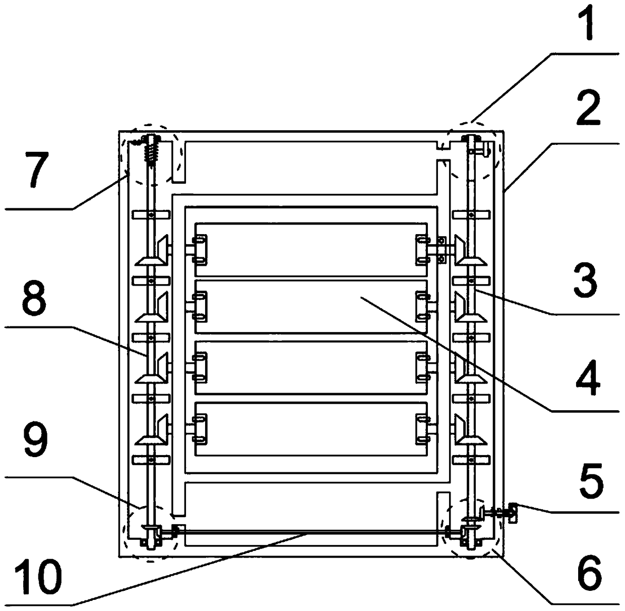
[0032] Combine below figure 1 , 2, 3, 4, 5, 6, 7, 8, 9, 10 illustrate this embodiment. The present invention relates to a window, more specifically a multifunctional solar shading window, including a limiter 1, a window frame 2, The right shaft 3, the visor 4, the manual valve 5, the manual and automatic conversion device 6, the reset device 7, the left shaft 8, the rotation transmission device 9, and the connecting rod 10 can not only use solar energy to heat the gas, but also make the gas volatilize to drive the visor to rotate ; And it can be restored automatically, and the angle of the visor can be manually adjusted.
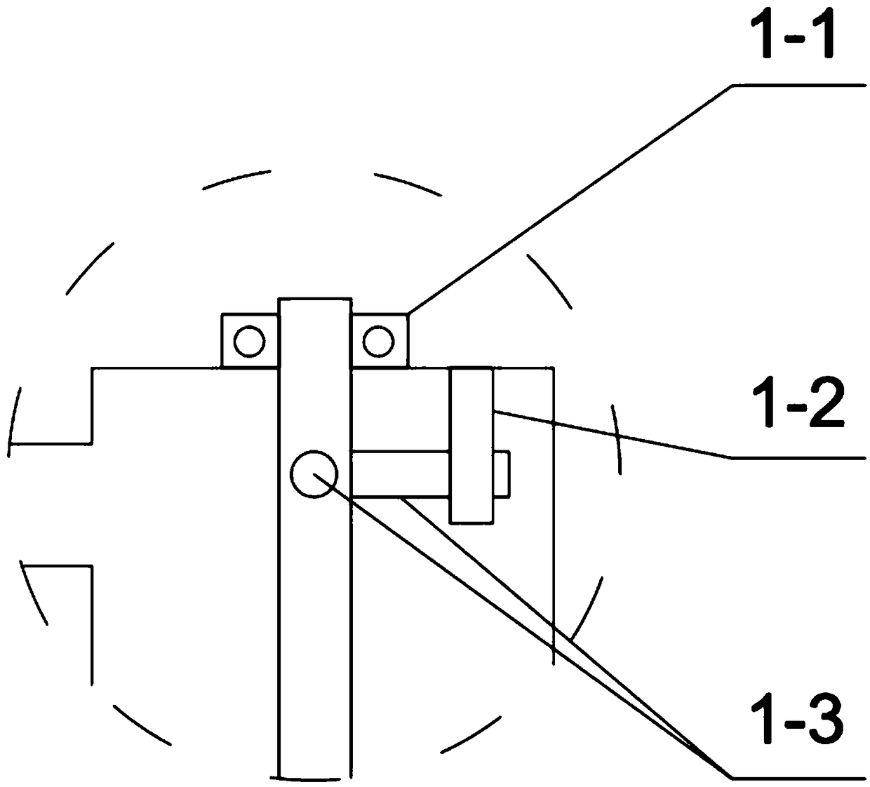
[0033] Limit 1 is composed of bearing 1-1 on the right rotating shaft, limit rod 1-2, and ninety degree limit rod 1-3; bearing 1-1 on the right rotating shaft is located at the upper right side of window frame 2, and bearing 1-1 passes through the upper part of the right rotating shaft 3; the limit rod 1-2 is a cylinder, the limit rod 1-2 is located on the...
specific Embodiment approach 2
[0042] Combine below figure 1 , 2 , 3, 4, 5, 6, 7, 8, 9, and 10 describe this embodiment, and this embodiment will further describe Embodiment 1, and an easily volatile inert gas is poured into the frame body 2 .
specific Embodiment approach 3
[0043] Combine below figure 1 , 2 , 3, 4, 5, 6, 7, 8, 9, and 10 illustrate this embodiment, and this embodiment will further describe Embodiment 1, and the connecting belt 3-5-2 is a soft plastic structure.
PUM
Abstract
The invention relates to a window, in particular to a multifunctional solar shading window. Gas can be heated by solar energy and evaporated to drive shading plates to rotate, the multifunctional solar shading window can automatically restore, and the angles of the shading plates can be manually adjusted. A window frame is rectangular, a left rotating shaft is mounted on the left side of the window frame, a right rotating shaft is mounted on the right side of the window frame, a connecting rod is mounted on the lower portion of the window frame, the right rotating shaft is positioned on the right side of the window frame, the upper portion of the right rotating shaft is connected with a limiter, the lower portion of the right rotating shaft is connected with a manual-automatic rotating ring device, the four shading plates are positioned in the middle of the window frame, a manual valve is positioned on the right lower side of the window frame and positioned on the right side of the right rotating shaft, a manual-automatic switching device is positioned on the lower portion of the right rotating shaft, the left side of the manual-automatic switching device is engaged with the connecting rod, a reset device is positioned on the left upper side of the window frame, the lower portion of the reset device is connected with the left rotating shaft, the left rotating shaft is positioned on the left side of the window frame, and the lower portion of the left rotating shaft is engaged with the connecting rod.
Description
technical field [0001] The invention relates to a window, in particular to a multifunctional solar shading window. Background technique [0002] Windows have changed from wooden frames to steel frames to the current plastic-steel windows, and the performance of the windows is also gradually enhanced. The current plastic-steel windows are not only easy to produce, but also have sound insulation and thermal insulation effects that are far better than in the past. But curtains at home take up a lot of space. So this multifunctional solar blackout window is designed. Contents of the invention [0003] The invention provides a multifunctional solar shading window, which has the beneficial effect of not only being able to use solar energy to heat the gas, so that the gas volatilizes to drive the shading plate to rotate; it can also automatically recover, and the angle of the shading plate can also be manually adjusted. [0004] In order to solve the above technical problems, t...
Claims
Application Information
Patent Timeline
Application Date:The date an application was filed.
Publication Date:The date a patent or application was officially published.
First Publication Date:The earliest publication date of a patent with the same application number.
Issue Date:Publication date of the patent grant document.
PCT Entry Date:The Entry date of PCT National Phase.
Estimated Expiry Date:The statutory expiry date of a patent right according to the Patent Law, and it is the longest term of protection that the patent right can achieve without the termination of the patent right due to other reasons(Term extension factor has been taken into account ).
Invalid Date:Actual expiry date is based on effective date or publication date of legal transaction data of invalid patent.