
Hydraulic hammer

A hydraulic hammer and pressure technology, applied in the field of hydraulic impact mechanism, can solve problems such as structural complexity, high cost, and low efficiency

Pending Publication Date: 2020-05-15
塔迪缇斯亚有限责任公司
View PDF5 Cites 0 Cited by
  • Summary
  • Abstract
  • Description
  • Claims
  • Application Information

AI Technical Summary

Problems solved by technology

[0003] The disadvantages of this impact mechanism are the complexity and high cost of its structure, low efficiency, and not removing heat directly from the heat source

Method used


Image

  • Hydraulic hammer
  • Hydraulic hammer
  • Hydraulic hammer

Examples


Embodiment Construction

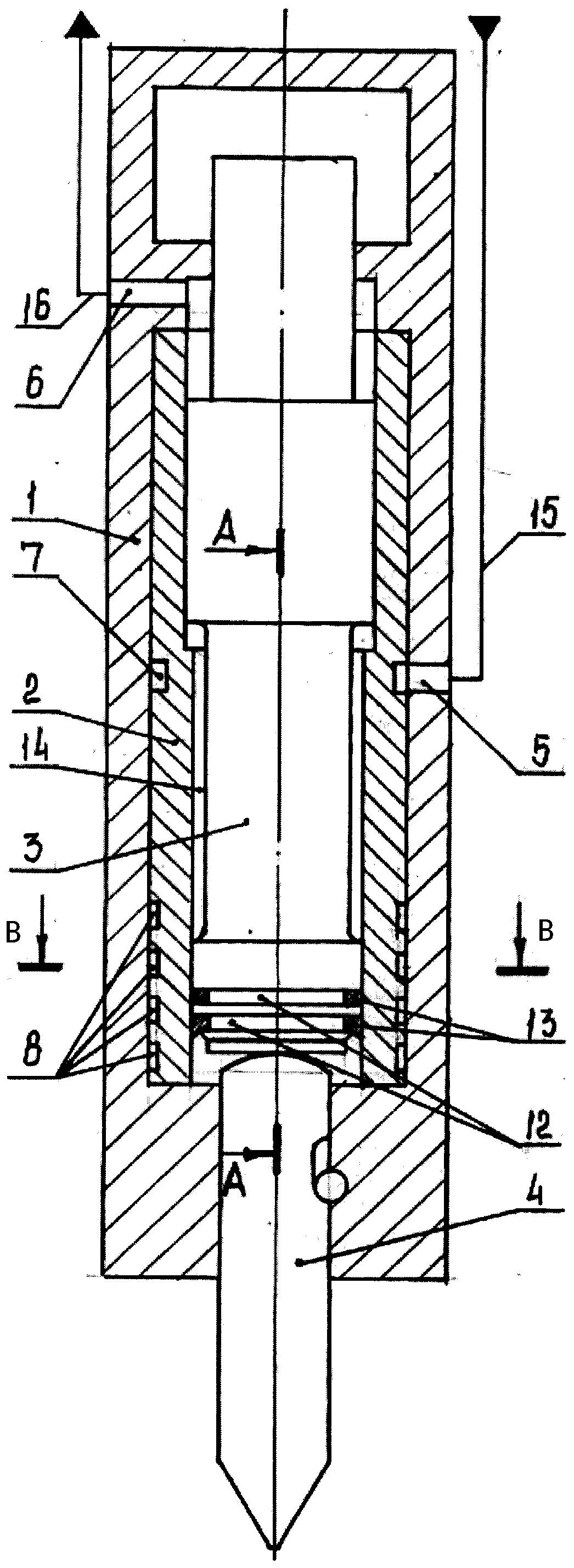
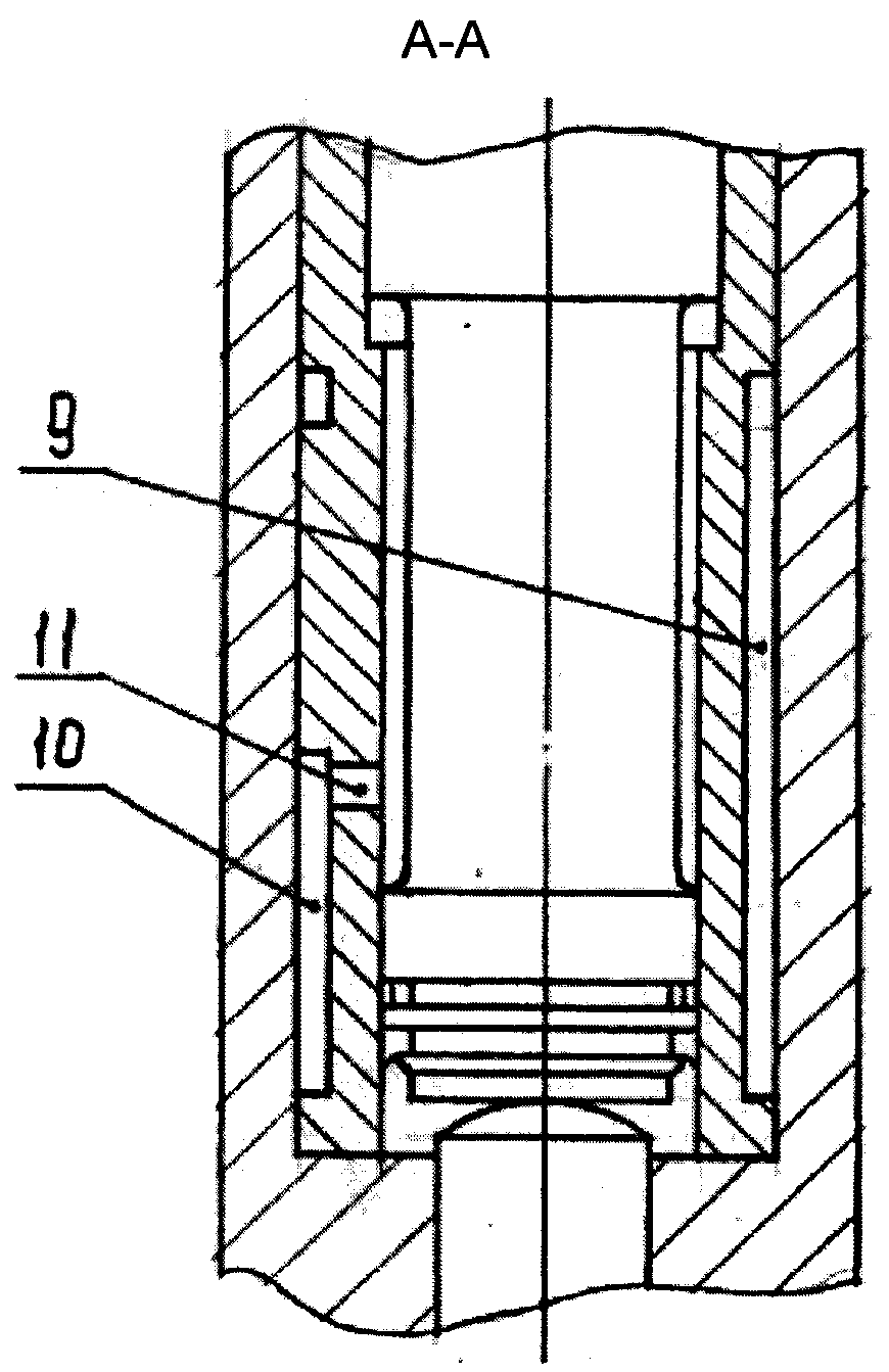
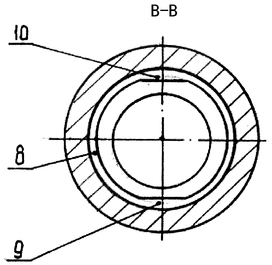
[0029] The hydraulic hammer includes a casing 1 , a sleeve 2 , a hammer head 3 and a work piece 4 .

[0030] Pressure holes 5 and relief holes 6 are made on the casing 1 .

[0031] On the outer surface of the sleeve 2 there are pressure cutouts 7 , a plurality of cutouts 8 and diametrically opposite first longitudinal grooves 9 and second longitudinal grooves 10 . The sleeve wall has pressure holes 11 connected to this longitudinal groove 10 .

[0032] At the lower part of the hammer head 3 there are a plurality of annular grooves 12 in which seals 13 are installed.

[0033] The sleeve 2 is installed in the casing 1 . The hammer head 3 is arranged in the sleeve 2, the pendant head reciprocates therein and forms a firing cavity 14 therewith.

[0034] The pressure hole 5 is connected to a pressure line 15 , and the discharge hole 6 is connected to a discharge line 16 .

[0035] The work piece 4 is mounted on the bottom of the hydraulic hammer.

[0036] During operation, the...


PUM


Abstract

The invention relates to the mining and construction industry and is directed toward increasing the operating efficiency and reliability of a hydraulic hammer by increasing heat transfer (cooling) andlowering the temperature both of the hydraulic hammer as a whole and of a liner thereof without complicating the structure of the hydraulic hammer. This technical result is achieved in a hydraulic hammer consisting of a housing having a pressure port and a drain port and having a liner disposed in said housing that has a pressure groove and a pressure port, a head that is disposed inside of the liner such that it can move reciprocally and that interacts with a working instrument, and a pressure line and a drain line, moreover, on the outer surface of the liner, there are annular grooves and two longitudinal canals, said canals being diametrically opposite one another.

Description

technical field [0001] This invention relates to the mining and construction industries, in particular to hydraulic percussion mechanisms, and is intended for use as mobile construction equipment and road building machines for breaking continuous rock, road surfaces, solidified concrete structures and the like. Background technique [0002] Hydraulic hammers known from the prior art comprise a high-voltage bushing in the wall of which there are a number of channels for communicating with the first and second set of holes and for supplying a fluid medium. This channel contains a porous medium to ensure hydraulic fluid flows through it. The porous structure is a honeycomb structure to increase the surface area, which increases the heat dissipation rate (US2017080554, March 23, 2017). [0003] Disadvantages of this type of impact mechanism are the complexity and high cost of their construction, low efficiency, and the fact that heat is not removed directly from the heat source...

Claims


Application Information

Patent Timeline
IPC IPC(8): B25D17/00
CPCB25D17/22B25D9/12B25D2250/231E02F3/966B25D17/00B25D9/00
Inventor 基里洛夫·基里尔·格恩纳德维奇
Owner 塔迪缇斯亚有限责任公司
Learn More