
Air ionization display device

A technology for air ionization and display devices, applied in measuring devices, material analysis through electromagnetic means, instruments, etc., can solve the problem that the display screen pixels of the air ionization system are difficult to increase, and achieve a good user experience and the effect of improving pixels

Pending Publication Date: 2020-05-15
ANHUI EASPEED TECHNOLOGY CO LTD
View PDF0 Cites 2 Cited by
  • Summary
  • Abstract
  • Description
  • Claims
  • Application Information

AI Technical Summary

Problems solved by technology

[0002] In the imaging process of the air ionization imaging system, the lens is used to converge the light beam and ionize the air at the focal point of the lens to form a light spot. Since the optical power threshold per unit area of ​​the pulse required to form air ionization is relatively high, then at each ionization point The number of focal points formed by the modulated light field of the spatial light modulator is limited by the pulse power, that is, the pixels of the display screen are limited by the size of the pulse power. If the pixels of the display screen are to be increased, the output pulse power of the light source needs to be further increased. However, it is difficult to greatly increase the output pulse power of the light source in the existing technology, which makes it difficult to increase the pixels of the display screen of the air ionization system.

Method used


Image

  • Air ionization display device
  • Air ionization display device
  • Air ionization display device

Examples


Embodiment Construction

[0041] Embodiments of the present invention are described in detail below, and examples of the embodiments are shown in the drawings, wherein the same or similar reference numerals denote the same or similar elements or elements having the same or similar functions throughout. The embodiments described below by referring to the figures are exemplary and are intended to explain the present invention and should not be construed as limiting the present invention.

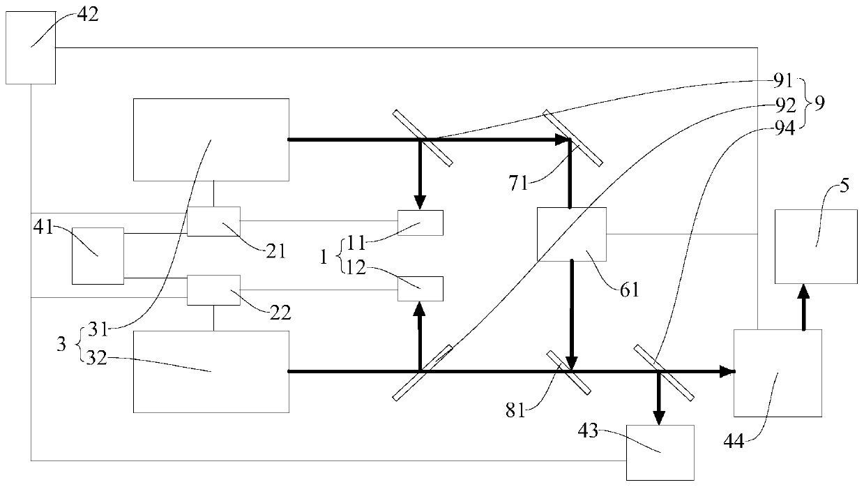
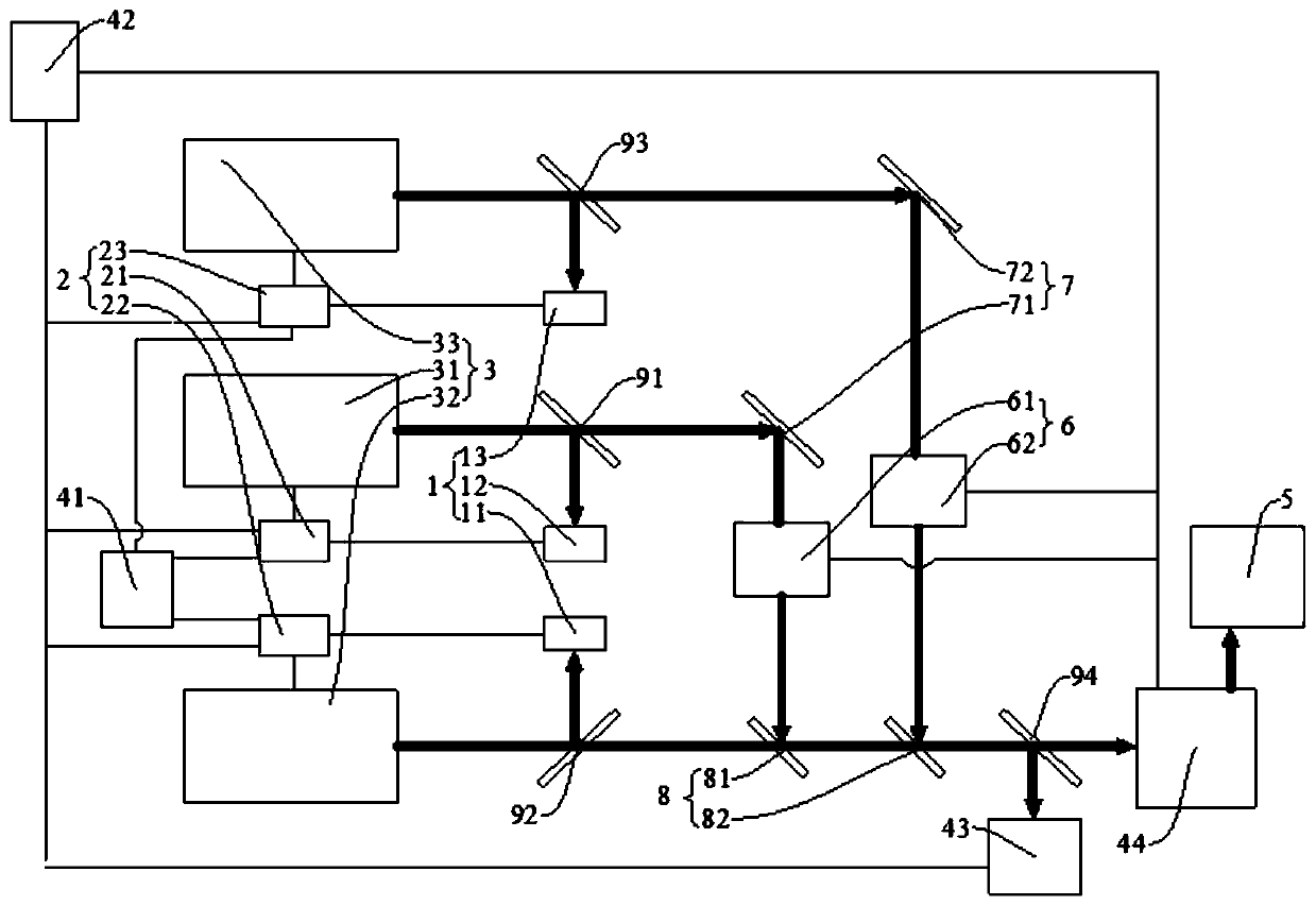
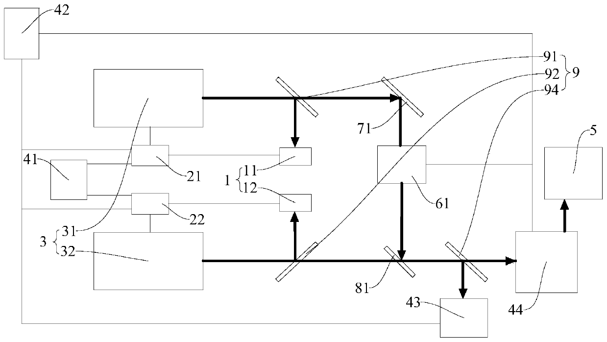
[0042] Refer below Figure 1-Figure 2 An air ionization based display device according to an embodiment of the present invention will be described.

[0043] The air ionization display device according to the embodiment of the present invention includes: a plurality of pulsed light sources 3 , a beam combiner 8 , a light field regulating component 44 and a controller 42 .

[0044] Among the multiple pulsed light sources, each pulsed light source 3 produces a pulsed beam, and the multiple beams of the multiple pulsed li...


PUM

PropertyMeasurementUnit
reflectanceaaaaaaaaaa

Abstract

The invention discloses an air ionization display device. The device comprises a plurality of pulse light sources, a beam combiner and a light field regulation and control assembly. Light beams generated by the pulse light sources are all projected on the beam combiner to be combined into one light beam, the light beams combined by the beam combiner are projected into the light field regulation and control assembly, and the light field regulation and control assembly regulates and aggregates the light beams and enables air to be ionized in a display area to form a holographic real image. According to the air ionization display device, through increasing the number of the pulse light sources, a beam combiner is used for combining the light beams of the plurality of pulse light sources and compensating time delay among pulses, it can be guaranteed that multiple pulses output by multiple pulse light sources appear at the same position and at the same time in a display area, and air is ionized. Therefore, the problems of space synchronization and time synchronization among a plurality of pulses output by the multi-pulse light source are solved, the pixels of an air ionization display picture can be multiplied, and good use experience is brought to a user.

Description

technical field [0001] The invention relates to the field of air display, in particular to an air ionization display device. Background technique [0002] In the imaging process of the air ionization imaging system, the lens is used to converge the light beam and ionize the air at the focal point of the lens to form a light spot. Since the optical power threshold per unit area of ​​the pulse required to form air ionization is relatively high, then at each ionization point The number of focal points formed by the modulated light field of the spatial light modulator is limited by the pulse power, that is, the pixels of the display screen are subject to the size of the pulse power. If the pixels of the display screen are to be increased, the output pulse power of the light source must be further increased. However, it is difficult to greatly increase the output pulse power of the light source in the existing technology, which makes it difficult to increase the pixels of the dis...

Claims


Application Information

Patent Timeline
Patent Type & Authority Applications(China)
IPC IPC(8): G01N27/62G02B27/10G02B26/08
CPCG01N27/628G02B27/10G02B26/08
Inventor 范超韩东成
Owner ANHUI EASPEED TECHNOLOGY CO LTD
Learn More