
Light-gathering type light-emitting sign

A luminous sign, concentrating technology, applied in the field of luminous signs, can solve the problems of lack of background design effect, lack of visual effect, etc., to achieve soft light, improve lighting effect, and enhance the effect of art display

Pending Publication Date: 2020-05-15
马飞
View PDF0 Cites 0 Cited by
  • Summary
  • Abstract
  • Description
  • Claims
  • Application Information

AI Technical Summary

Problems solved by technology

And some luminous signs are designed as art and visual effects. The design of the local background where the luminous signs are located is designed as a whole that complements and cooperates with the luminous patterns. Both are indispensable.
However, after the luminous pattern is luminous, the effect specially designed for the background is visually missing, which is a shortcoming in visual effect

Method used


Image

  • Light-gathering type light-emitting sign
  • Light-gathering type light-emitting sign
  • Light-gathering type light-emitting sign

Examples


Embodiment

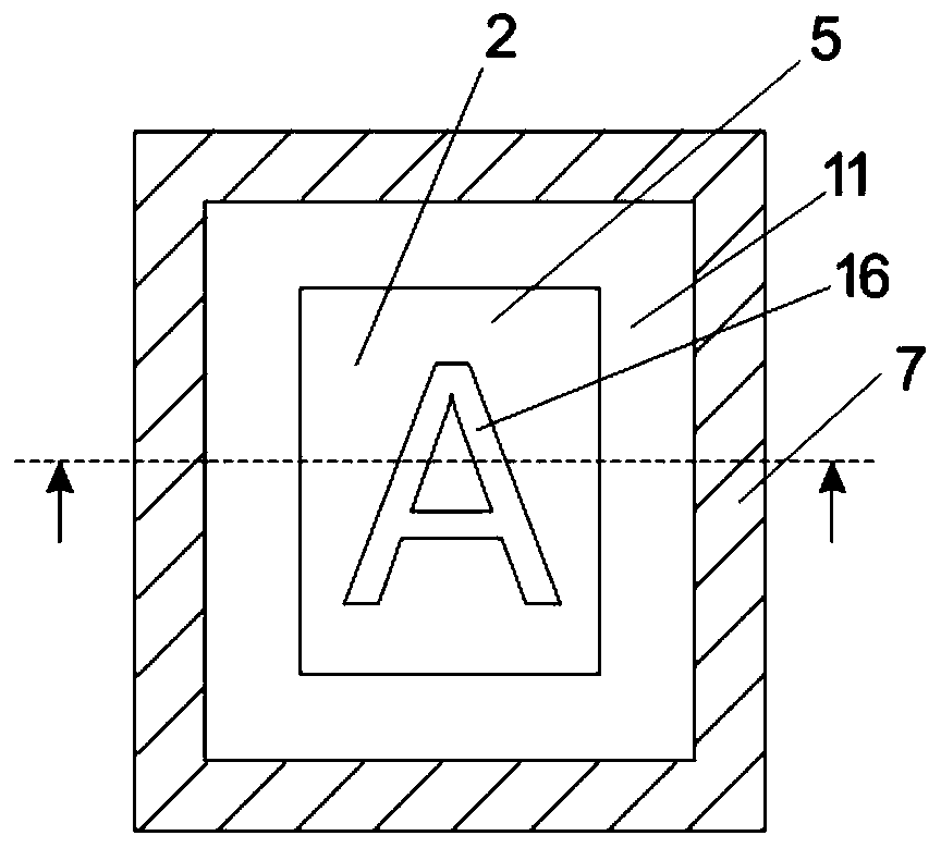
[0055] Such as Figure 1A and Figure 1B As shown, this embodiment provides a concentrating light-emitting sign in which the shape of the concentrating groove 2 is a rectangle (that is, a closed-loop structure), including: a substrate 5, a light source, a frame 7, a surface finish layer 11, a spacer 12, a positive Light-emitting structure and side-to-side condenser lens structure 3;

[0056] The manufacturing method of frame 7: enclose the frame 7 that has rectangular hollow structure in the middle with the non-translucent strip profile (comprising wood or metal or plastic) of " L " shape with section, the front of frame 7 has frame eaves 13 structures. Optionally, the frame 7 can be made with an inverted "U"-shaped strip profile, such as Figure 1E Border 7 shown.

[0057] Manufacturing method of the light source: the light source related to the forward light-emitting structure is the first light source 6 , and the light source related to the side light-concentrating struct...


PUM


Abstract

The invention relates to the field of light-gathering type light-emitting signs, and provides a light-gathering type light-emitting sign, which comprises a substrate, a light source, a forward light-emitting structure and a lateral light-gathering structure. A light-gathering groove is defined by a light outlet port in the lateral light-gathering structure. The substrate is arranged below the light-gathering groove, a sinking light-gathering space is formed between the light-gathering groove and the substrate, the forward light-emitting structure is arranged on the substrate in the sinking light-gathering space, a light source related to the forward light emitting structure is a first light source, and the first light source emits light to display a longitudinal upward light emitting pattern through the forward light emitting structure; a light source related to the lateral light-gathering n structure is a second light source, and the second light source emits light to the surface of the substrate located in the sinking light-gathering space and the forward light emitting structure through a light outlet port of the lateral light-gathering structure to centralize and transversely emit light rays; the whole sinking light-gathering space is filled with light scattered by the lateral light-gathering structure and the forward light-emitting structure, the light is soft, no dead angle exists, the defect that the peripheral area of a light-emitting pattern is dark and inconvenient to observe due to the fact that the brightness of the forward light-emitting pattern is high in thepast is overcome, and the visual effect of the overall structure is improved by designing the surface material or color or pattern of the substrate and matching with the forward light-emitting pattern.

Description

technical field [0001] The invention relates to the field of luminous signs, in particular to a concentrating luminous sign. Background technique [0002] Traditional forward luminous signs are generally set up in dark places, such as bars or nightclubs. After the luminous sign is illuminated, due to the strong luminescence of the forward luminous pattern, the environment where the luminous sign is located and the background around the luminous pattern are basically invisible due to the strong contrast of light. Some luminous signs are designed as art and visual effects, and the design of the local background where the luminous sign is located is designed as a whole that complements and cooperates with the luminous pattern, and both are indispensable. However, after the luminous pattern is luminous, the effect specially designed for the background is visually missing, which is a shortcoming in visual effect. Contents of the invention [0003] The purpose of the present i...

Claims


Application Information

Patent Timeline
Patent Type & Authority Applications(China)
IPC IPC(8): A47G1/06F21V33/00
CPCA47G1/0622F21V33/00
Inventor 不公告发明人
Owner 马飞
Learn More