
Physical layer safety optimization power distribution method in 5G NOMA system

A 5GNOMA, physical layer security technology, applied in the field of physical layer security optimization power distribution in 5GNOMA system, can solve the problems of eavesdropping, internal eavesdropping, inability to decode the information of remote users, etc. Effect

Active Publication Date: 2020-05-12
XIDIAN UNIV +1
View PDF4 Cites 9 Cited by
  • Summary
  • Abstract
  • Description
  • Claims
  • Application Information

AI Technical Summary

Problems solved by technology

Through this method, each user can obtain all transmission signals after passing through SIC, but each user can only obtain their own private information
In short, by using a special sequence to convert the data of the far-end user to another domain, so that the near-end user can demodulate the signal of the far-end user through SIC, but it cannot decode the information of the far-end user to achieve eavesdropping. Effect
[0007] To sum up, the problems existing in the existing technology are: in the NOMA technology, due to the nature of the SIC itself, the difference in power distribution leads to the difference in the demodulation sequence of the communication system, and the near-end user may conduct internal eavesdropping on the far-end user, forming a Certain security risks; and the existing solution is to convert the data of the remote user to another domain to prevent internal eavesdropping, rather than simply operating in the power domain
[0008] Difficulty in solving the above technical problems: How to optimize the security rate only by power distribution without switching domains, so as to prevent near-end users from eavesdropping on far-end users. There are no important related patents and related literature

Method used

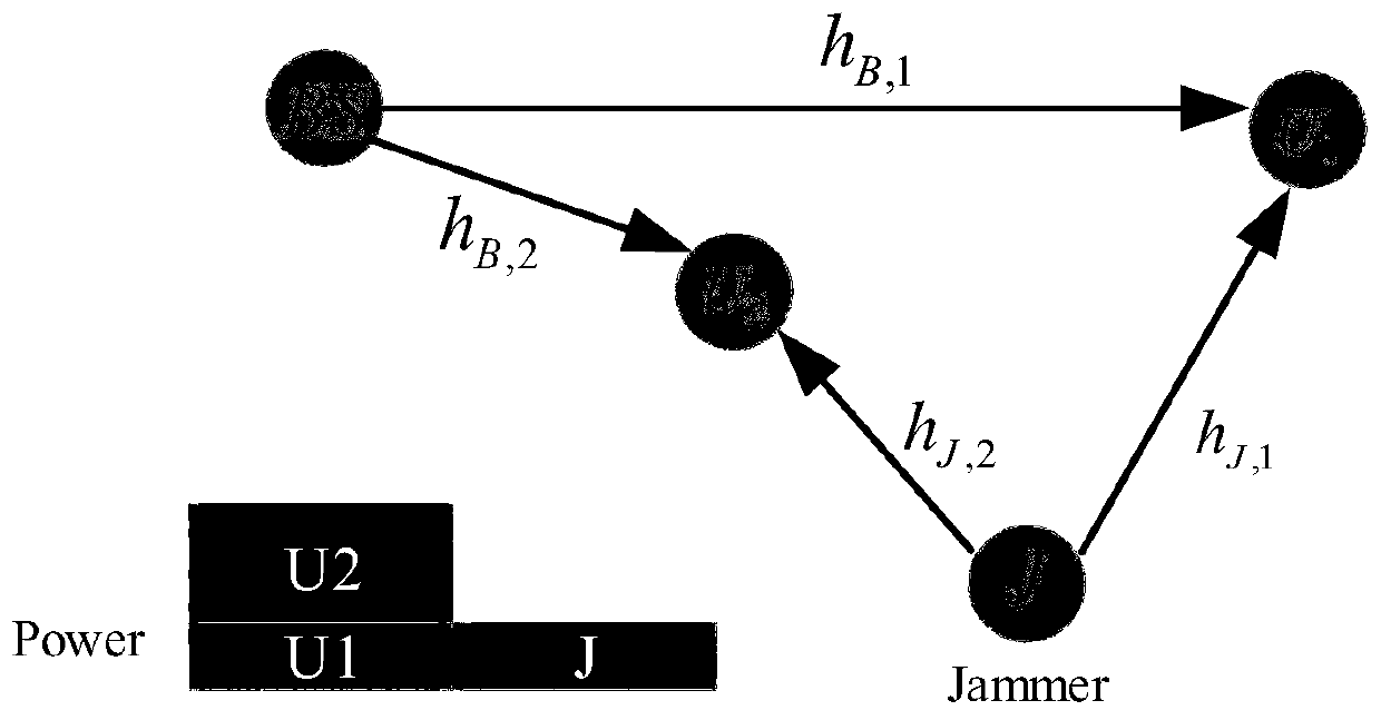
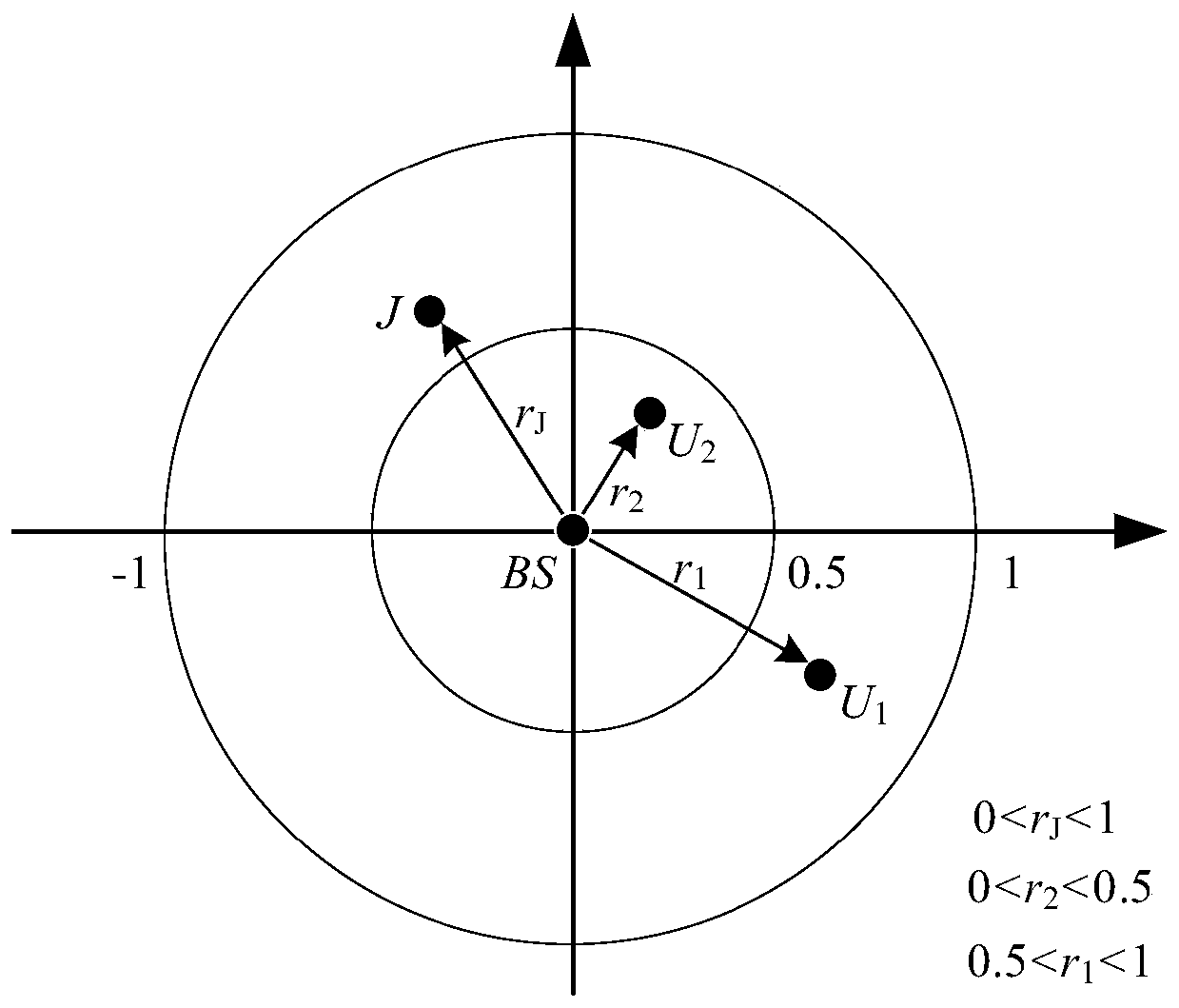

Image

  • Physical layer safety optimization power distribution method in 5G NOMA system
  • Physical layer safety optimization power distribution method in 5G NOMA system
  • Physical layer safety optimization power distribution method in 5G NOMA system

Examples


Embodiment Construction

[0045] In order to make the object, technical solution and advantages of the present invention more clear, the present invention will be further described in detail below in conjunction with the examples. It should be understood that the specific embodiments described here are only used to explain the present invention, not to limit the present invention.

[0046] Aiming at the problems existing in the prior art, the present invention provides a physical layer security optimized power allocation method in a 5G NOMA system. The present invention will be described in detail below in conjunction with the accompanying drawings.

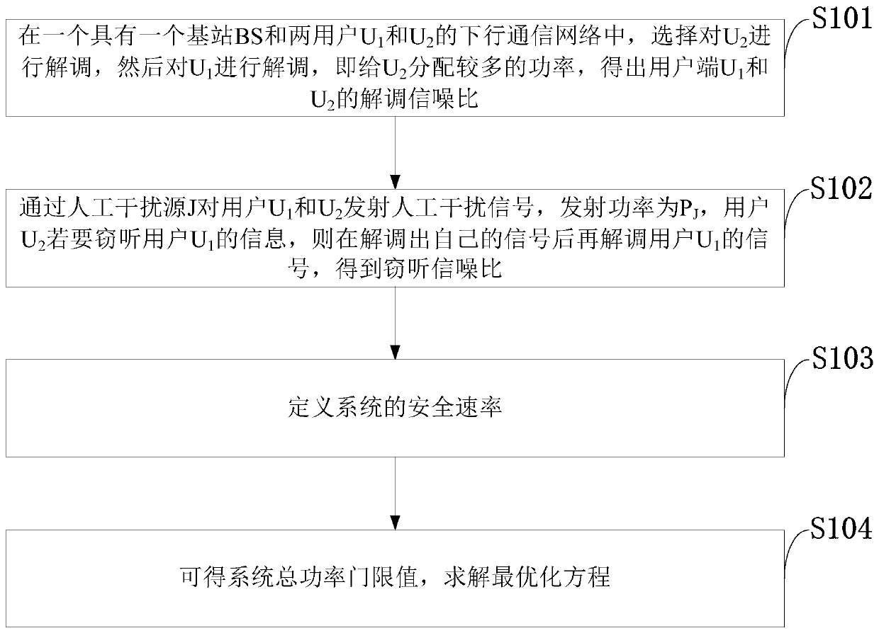
[0047] Such as figure 1 As shown, the physical layer security optimal power allocation method in the 5GNOMA system provided by the embodiment of the present invention includes the following steps:

[0048] S101: In a base station BS and two users U 1 and U 2 In the downlink communication network, select the U 2 demodulation, and then the U 1 demodula...


PUM


Abstract

The invention belongs to the technical field of wireless communication, and discloses a physical layer safety optimization power distribution method in a 5G NOMA system. In a downlink communication network with a base station BS and two users U1 and U2, a near-end user U2 is selected to be demodulated, then a far-end user U1 is demodulated, more power is distributed to U2, and the demodulation signal-to-noise ratio of the user ends U1 and U2 is obtained; an artificial interference source J is used for transmitting an artificial interference signal to the user U1 and the user U2, the transmitting power is PJ, and if the user U2 wants to eavesdrop information of the user U1, the user U2 demodulates the signal of the user U1 after demodulating the signal of the user U2 to obtain an eavesdropsignal-to-noise ratio; the security rate of the system is defined; the total power threshold value of the system can be obtained, and an optimization equation is solved. An optimization equation is constructed according to system limiting conditions, the threshold value of the total power is obtained through solving and power distribution selection is carried out according to the threshold value.

Description

technical field [0001] The invention belongs to the technical field of wireless communication, and in particular relates to a method for optimizing power allocation for physical layer security in a 5G NOMA system. Background technique [0002] Currently, the closest existing technology: With the advent of the fifth generation mobile communication (5G) era, NOMA technology as its core technology has become a hot development trend. [0003] "Furqan, Haji M., J.M.Hamamreh, and H.Arslan."Physical Layer Security for NOMA: Requirements, Merits, Challenges, and Recommendations."(2019). OMA) technology, NOMA technology allocates resources in a non-orthogonal way to support large-scale connections and improve spectrum utilization. Now NOMA has two types of solutions, namely power domain NOMA technology (PD- NOMA) and NOMA technology in code domain (CD-NOMA). [0004] In the NOMA technology of power domain multiplexing, in order to provide users with good quality of service (QoS), c...

Claims


Application Information

Patent Timeline
IPC IPC(8): H04W12/02H04W12/12H04W16/22H04W52/30H04W72/04
CPCH04W12/02H04W12/12H04W16/22H04W52/30H04W72/0473
Inventor 张沉思张哲刘玉涛葛建华贾凡
Owner XIDIAN UNIV
Learn More