
Battery cell

A battery pack and battery technology, applied in the field of battery pack batteries, can solve the problems of uniform cooling, unsatisfactory use of structural space, etc., and achieve the effect of reducing weight

Active Publication Date: 2020-05-12
VOLKSWAGEN AG
View PDF7 Cites 2 Cited by
  • Summary
  • Abstract
  • Description
  • Claims
  • Application Information

AI Technical Summary

Problems solved by technology

Here, the ratio of length to radius can only be adjusted to a limited extent
The large number of smaller round cells requires a large number of peripheral devices for fastening, electrical connection, cooling, etc., so that the limited available installation space can only be used unfavorably
The small number of larger circular cells has the disadvantage that uniform cooling of the larger circular cells is problematic

Method used


Image

  • Battery cell
  • Battery cell
  • Battery cell

Examples


Embodiment Construction

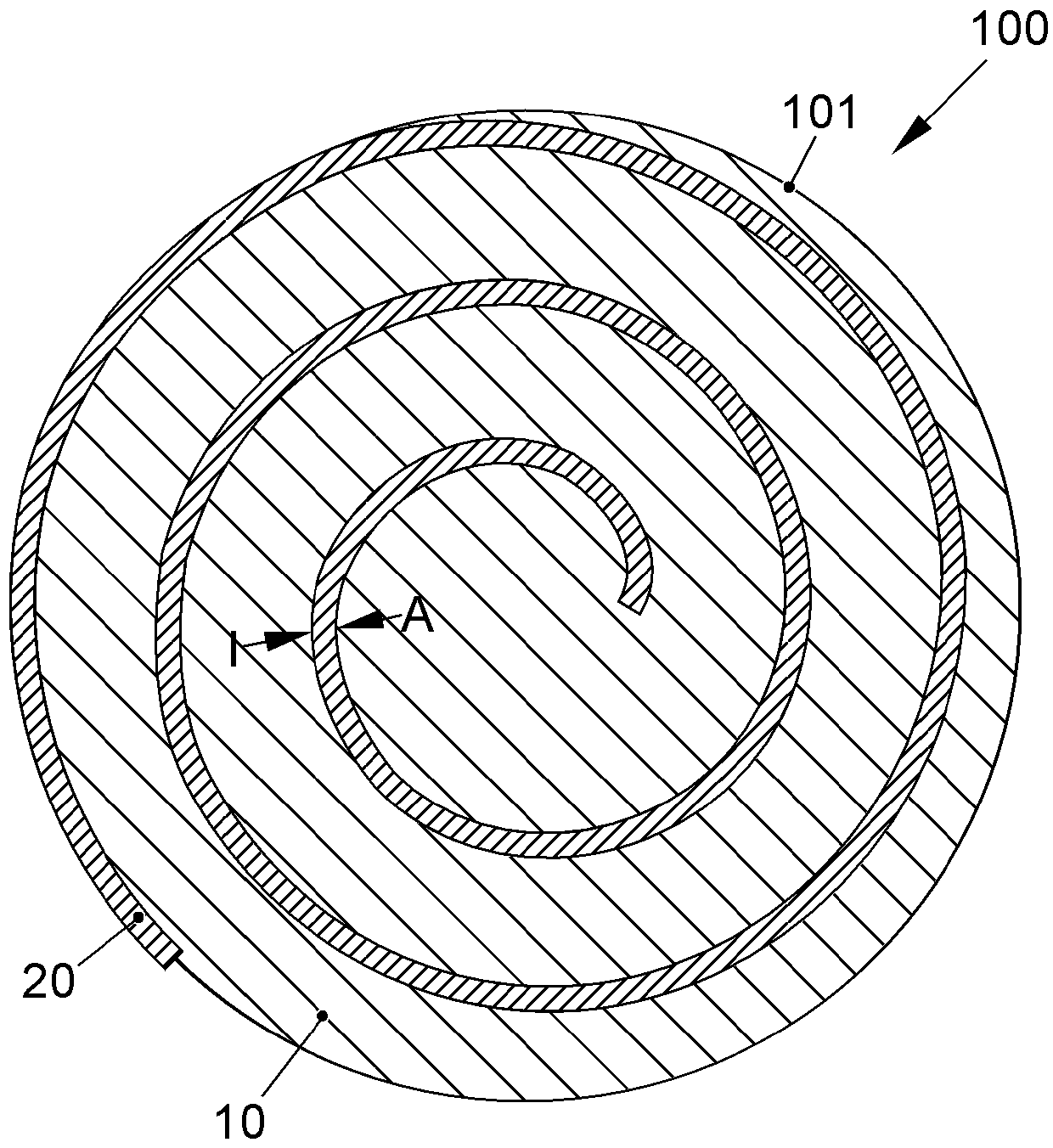
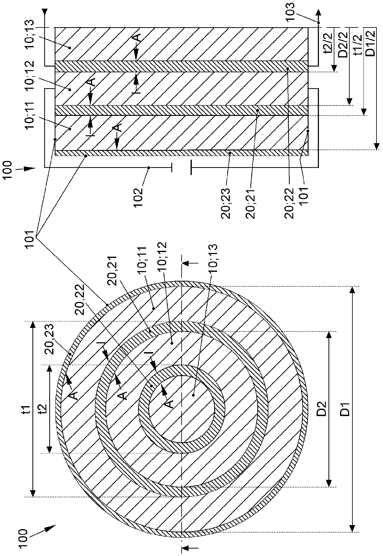
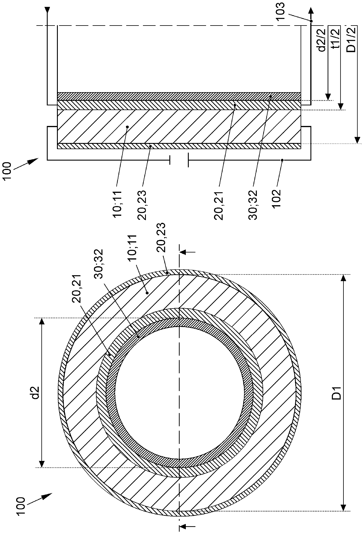
[0046] Figures 1 to 5 The battery cell 100 is shown in the form of a circular cell. The battery cell 100 has at least one electrode element 10 with an inner side I and an outer side A and at least one temperature control element 20 . According to the invention it is provided that the inner side I of the at least one electrode element 10 is spaced at least in sections from the outer side A of the at least one electrode element 10 by means of the temperature control element 20 .

[0047] Follow all attached Figures 1 to 5 The battery cell 100 has at least one electrode element 10 . exist figure 2 In an embodiment, the battery cell 100 can have only one, preferably strip-shaped, electrode element 10 which can be wound into a roll. exist figure 1 In an embodiment, the battery cell 100 can have a plurality of, preferably cylindrical sleeve-shaped, electrode elements 10 which can be inserted into one another. Here, a first electrode element 11 , a second electrode element 1...


PUM


Abstract

A battery cell 100 in the form of a round cell, having: at least one electrode element 10 having an inner side I and an outer side A and at least one temperature control element 20, wherein the innerside of the at least one electrode element 10 is spaced apart, at least in sections, from the outer side A of the at least one electrode element 10 by means of the temperature control element 20.

Description

technical field [0001] The invention relates to a battery cell in the form of a round cell (Rundzelle) according to the preamble of the independent device claim and a method for producing a round cell according to the independent method claim A method of forming a battery cell. Background technique [0002] The goal pursued in battery pack development is to design the battery pack and the individual battery cells as large as possible and to design the enclosure as small as possible so that all mechanical Load condition. In order to achieve maximum power density and energy density, the structural components must be designed in a space-saving and as far as possible without redundancy. At the same time, in addition to the installation space for the battery cells, sufficient installation space must be maintained within the housing for electrical wiring and control devices. The battery cells must in turn have the best possible thermal contact with the cooling device. Likewise...

Claims


Application Information

Patent Timeline
Patent Type & Authority Applications(China)
IPC IPC(8): H01M10/613H01M10/617H01M10/625H01M10/643H01M10/654H01M10/04B60L50/64B60L58/26H01M50/213H01M50/24H01M50/249
CPCH01M10/613H01M10/617H01M10/625H01M10/643H01M10/654H01M10/0422B60L50/64B60L50/66B60L58/26H01M2220/20H01M50/24H01M50/249H01M50/213H01M10/0431Y02T10/70Y02E60/10Y02P70/50H01M10/653H01M50/20
Inventor V.霍姆B.沙尔F.韦舍J.考夫曼H.赫尔滕
Owner VOLKSWAGEN AG
Learn More