Eureka AIR delivers breakthrough ideas for toughest innovation challenges, trusted by R&D personnel around the world.

High-efficiency garbage burning power generation device

A waste combustion and power generation device technology, which is applied in the direction of combustion method, combustion type, steam generation method using pressure combustion, etc., can solve problems such as insufficient combustion, waste of combustion heat, and insufficient use of heat, so as to avoid insufficient incineration , Improve combustion efficiency, increase the effect of burning difficulty

Inactive Publication Date: 2020-05-12
YUYAO XINZHI NEW ENERGY TECH CO LTD
View PDF0 Cites 0 Cited by
  • Summary
  • Abstract
  • Description
  • Claims
  • Application Information

AI Technical Summary

Problems solved by technology

Garbage incineration can eliminate various pathogens, convert harmful substances into harmless substances, and can use the heat generated to generate electricity while incinerating garbage. The water in the steam is vaporized, and the steamed water is used to drive the steam turbine to generate electricity. The existing waste combustion power generation device does not fully utilize the heat generated by the waste combustion, resulting in a considerable part of the heat loss, resulting in a waste of combustion heat; in addition, there are Problems such as insufficient combustion and environmental pollution

Method used


Image

  • High-efficiency garbage burning power generation device
  • High-efficiency garbage burning power generation device
  • High-efficiency garbage burning power generation device

Examples


Embodiment Construction

[0017] All features disclosed in this specification, or steps in all methods or processes disclosed, may be combined in any manner, except for mutually exclusive features and / or steps.

[0018] Combine below Figure 1-4 The present invention is described in detail, and for convenience of description, the orientations mentioned below are now stipulated as follows: figure 1 The up, down, left, right, front and back directions of the projection relationship itself are the same.

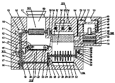
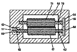
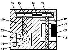
[0019] A high-efficiency garbage combustion power generation device of the device of the present invention includes a base body 10. A crushing chamber 60 with an upward opening is provided in the base body 10. A crushing mechanism 101 is provided in the crushing chamber 60. A crushing mechanism 101 is provided in the crushing chamber 60. There is a first rectangular groove 63, a second rectangular groove 59 is provided on the right side of the crushing chamber 60, a conveying chamber 12 communicating wi...


PUM


Abstract

The invention discloses a high-efficiency garbage burning power generation device. The high-efficiency garbage burning power generation device comprises a base body; a crushing cavity with an upward opening is formed in the base body; a crushing mechanism is arranged in the crushing cavity; a first rectangular groove is formed in the left side of the crushing cavity; a second rectangular groove isformed in the right side of the crushing cavity; a transferring cavity which communicates with the crushing cavity is formed below the crushing cavity; a transferring mechanism is arranged in the transferring cavity; a transmission cavity is arranged on the left side of the transferring cavity; a transmission mechanism is arranged in the transmission cavity; a third rectangular groove is formed in the rear side of the transmission cavity; a first driving shaft is rotatably arranged between the third rectangular groove and the transmission cavity; the front end of the first driving shaft extends into the transmission cavity and is fixedly provided with a first bevel gear; the rear end of the first driving shaft extends into the third rectangular groove and is fixedly provided with a firstbelt pulley; a fourth rectangular groove is formed below the transmission cavity; and a fifth rectangular groove is formed in the right side of the fourth rectangular groove.

Description

technical field [0001] The invention relates to the technical field of power generation, in particular to a high-efficiency garbage combustion power generation device. Background technique [0002] Waste-to-energy refers to a form of power generation that burns municipal solid waste through a special incineration boiler, and then generates power through a steam turbine generator set. The problem of garbage disposal has gradually become one of the focuses of widespread social attention. The most effective way of garbage disposal is landfill and incineration. Garbage incineration can eliminate various pathogens, convert harmful substances into harmless substances, and can use the heat generated to generate electricity while incinerating garbage. The water in the steam is vaporized, and the steamed water is used to drive the steam turbine to generate electricity. The existing waste combustion power generation device does not fully utilize the heat generated by the waste combus...

Claims


Application Information

Patent Timeline
IPC IPC(8): F23G5/033F23G5/44F23G5/46F23J1/00F23J15/02F22B1/22F22D11/06F01D15/10
CPCF01D15/10F22B1/22F22D11/06F23G5/033F23G5/44F23G5/444F23G5/46F23G2201/80F23J1/00F23J15/022F23J15/025Y02E20/12
Inventor 不公告发明人
Owner YUYAO XINZHI NEW ENERGY TECH CO LTD
Why Eureka
Eureka Blog
Learn More