Laminate cooling structure adopting polygonal turbulent flow columns
A technology of cooling structure and spoiler column, applied in the direction of supporting elements of blades, engine elements, machines/engines, etc., can solve the problems of increased heat load of turbine components, reduce flow resistance and flow loss, and achieve good heat exchange effect , Avoid the effects of backflow and streaming
- Summary
- Abstract
- Description
- Claims
- Application Information
AI Technical Summary
Problems solved by technology
Method used
Image

Examples
Embodiment 1
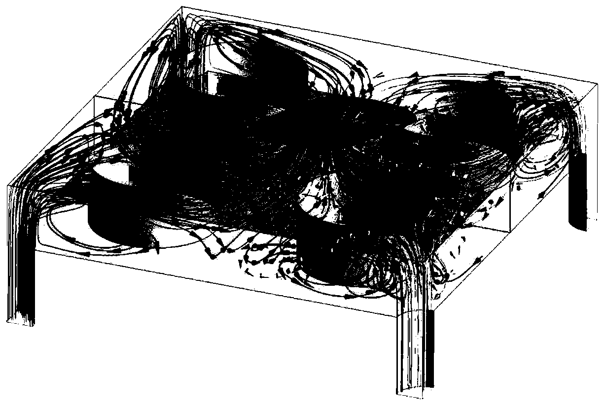
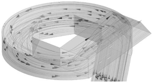
[0032] The present invention conducts a comparative study of the flow state of the internal cooling air between the conventional laminate structure and the interior cavity of the polygonal spoiler column laminate in the present invention through three-dimensional numerical simulation, as shown in Figure 2(a) and Figure 2(b), it can be It is known that the spiral cavity and the air inlet / outlet hole are smoothly connected and the turning angle is small, and there is no obvious change in cross-sectional area, so that the airflow will not appear sudden expansion and throttling, as well as mutual impact interference, and also make the laminate resistance smaller. The structure of the present invention is calculated and analyzed through numerical simulation, and its flow resistance is about 13% smaller than that of the conventional laminate structure, which confirms the above conclusion.
Embodiment 2
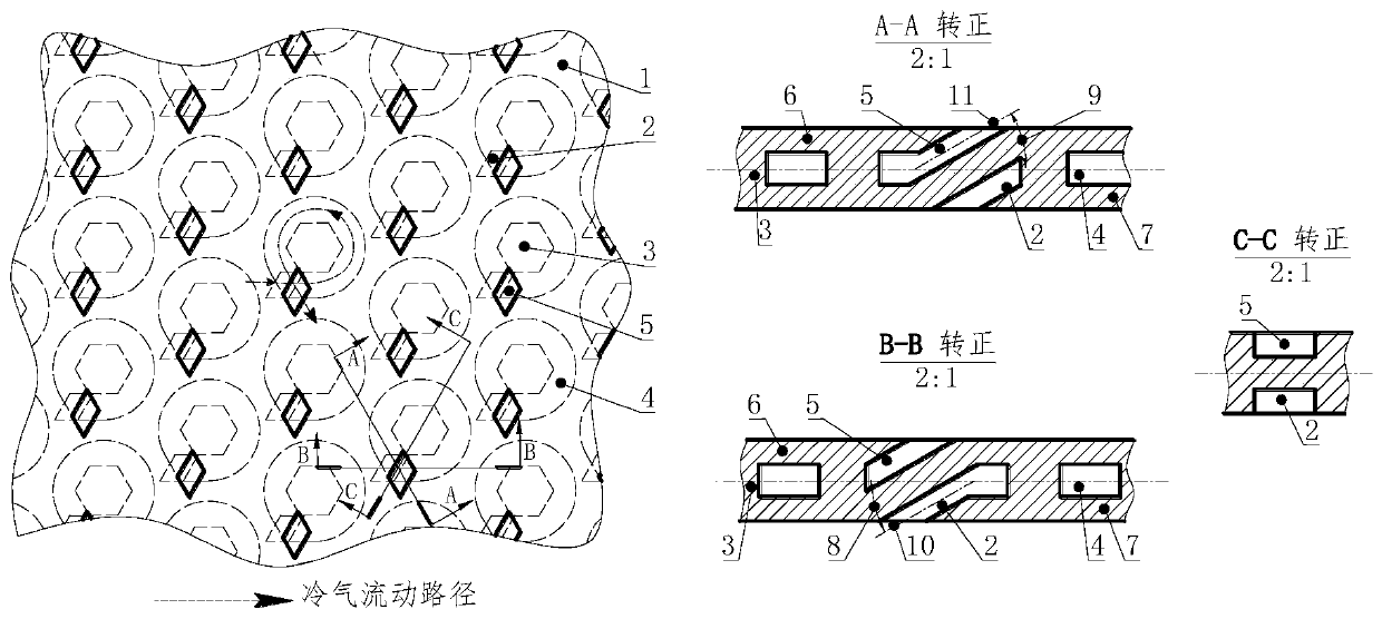
[0034] Such as figure 1 As shown, the present invention is a laminar cooling structure suitable for gas turbine engines, wherein the structure of the spoiler column 3 and the spiral cavity 4 is the main feature different from the existing laminar structure. Each spiral cavity is approximately circular and can be regarded as a relatively independent minimum unit body. The spoiler column 3 at the center of the unit body is a polygon, such as a triangle, a quadrangle, a pentagon, etc. (such as Figure 6 shown). The cavity structure around the spoiler column in the unit body is smoothly connected with the air inlet / outlet holes and generally presents a spiral shape. The air inlet hole 2 and the air outlet hole 5 which are spatially adjacent but do not interfere with each other have a parallelogram in section. The projections of the air inlet centerline 10 and the air outlet centerline 11 of the air inlet 2 and the air outlet 5 in each unit body in the horizontal plane are respe...
Embodiment 3
[0038] The present invention is a laminar cooling structure suitable for gas turbine engines, in which the structure of the spoiler column 3 and the spiral cavity 4 is the main feature different from the existing laminar structure. Each spiral cavity is approximately circular and can be regarded as a relatively independent minimum unit body, and the spoiler column 3 at the center of the unit body is hexagonal. The cavity structure around the spoiler column in the unit body is smoothly connected with the air inlet / outlet holes and generally presents a spiral shape. The air inlet 2 and the air outlet 5, which are spatially adjacent but do not interfere with each other, have a cross-section approximately parallelogram. The projections of the air inlet centerline 10 and the air outlet centerline 11 of the air inlet 2 and the air outlet 5 in each unit body are located in the horizontal plane, which are respectively parallel to the adjacent two sides of the spoiler column, and the a...
PUM
 Abstract
Description
Claims
Application Information
 - Generate Ideas
- Intellectual Property
- Life Sciences
- Materials
- Tech Scout
- Unparalleled Data Quality
- Higher Quality Content
- 60% Fewer Hallucinations
Browse by: Latest US Patents, China's latest patents, Technical Efficacy Thesaurus, Application Domain, Technology Topic, Popular Technical Reports.
© 2025 PatSnap. All rights reserved.Legal|Privacy policy|Modern Slavery Act Transparency Statement|Sitemap|About US| Contact US: help@patsnap.com