Connecting structure and construction method of steel ribs and hoops of steel rib concrete structure column

A steel-reinforced concrete and connection structure technology, applied in the direction of structural elements, columns, pier columns, etc., can solve the problems of long construction time, increase the difficulty of construction work for construction personnel, and high labor intensity, so as to improve construction quality and avoid welding quality problem, overall good effect

Inactive Publication Date: 2020-05-12
THE FIRST CONSTR CO LTD OF CHINA CONSTR FIRST GRP +1
View PDF7 Cites 6 Cited by
  • Summary
  • Abstract
  • Description
  • Claims
  • Application Information

AI Technical Summary

Problems solved by technology

[0004] In the above-mentioned prior art, the stirrups include shaped steel stirrups. In the first connection structure of the shaped steel stirrups, one end of the shaped steel stirrups is pierced with a stirrup hole and hooked to the rib plate, and the shaped steel stirrups are connected by iron wires. The ribs are tied to the floor, and the other end of the shaped steel stirrup is hooked to the corresponding steel bar. However, the above-mentioned shaped steel stirrups are open-type stirrups that are independent of each other. The construction personnel need to connect the open-type stirrups many times, and the construction time is relatively long. It is long and labor-intensive; in the second connection structure of the shaped steel stirrup, the shaped steel stirrup is set as a closed stirrup, and the closed stirrup is pierced with multiple stirrup holes at the same time, that is, the closed stirrup is set Corresponding stirrup holes are pierced on the outer peripheral side of the steel bars to form a closed-loop enclosure structure. Although the construction efficiency and structural strength are improved to a certain extent, it also increases the construction work difficulty of the construction workers. The existing Technology can be improved

Method used


Image

  • Connecting structure and construction method of steel ribs and hoops of steel rib concrete structure column
  • Connecting structure and construction method of steel ribs and hoops of steel rib concrete structure column
  • Connecting structure and construction method of steel ribs and hoops of steel rib concrete structure column

Examples


Embodiment 1

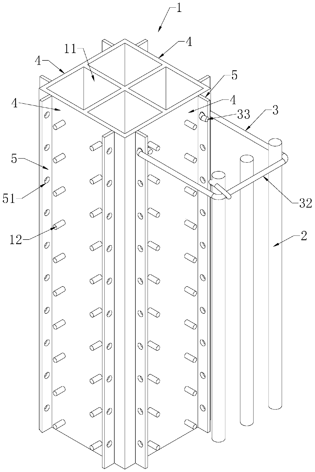
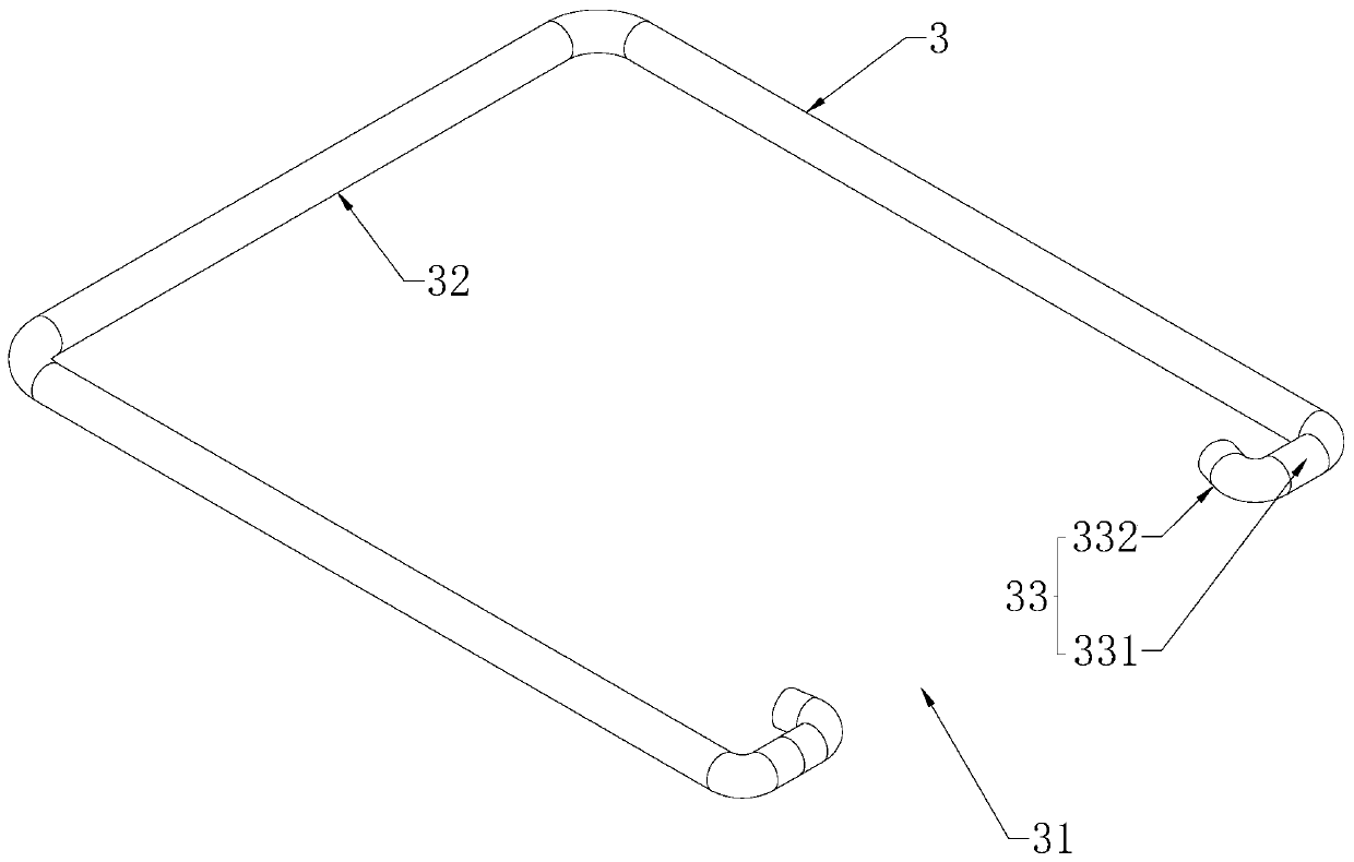
[0040] combine figure 1 and figure 2 As shown, a steel concrete structural column and stirrup connection structure includes a vertical welded and fixed steel frame column 1, and a number of longitudinal steel bars 2 are arranged and fixed on the peripheral side of the steel frame column 1 according to the design requirements, and the steel frame A stirrup 3 is connected between the steel bone column 1 and the longitudinal steel bar 2 . In this embodiment, the shaped steel column 1 is set as a box-shaped steel, and the box-shaped steel includes four first webs 4 that are vertically arranged and welded into a longitudinally extending box structure, and the inside of the box-shaped steel Welding has the cross-shaped framework 11 that plays a reinforcing role. The first web 4 is welded with a stirrup connecting plate 5 at the left and right symmetrical positions along its width direction, and the stirrup connecting plate 5 is welded and fixed on the outer surface of the first w...

Embodiment 2

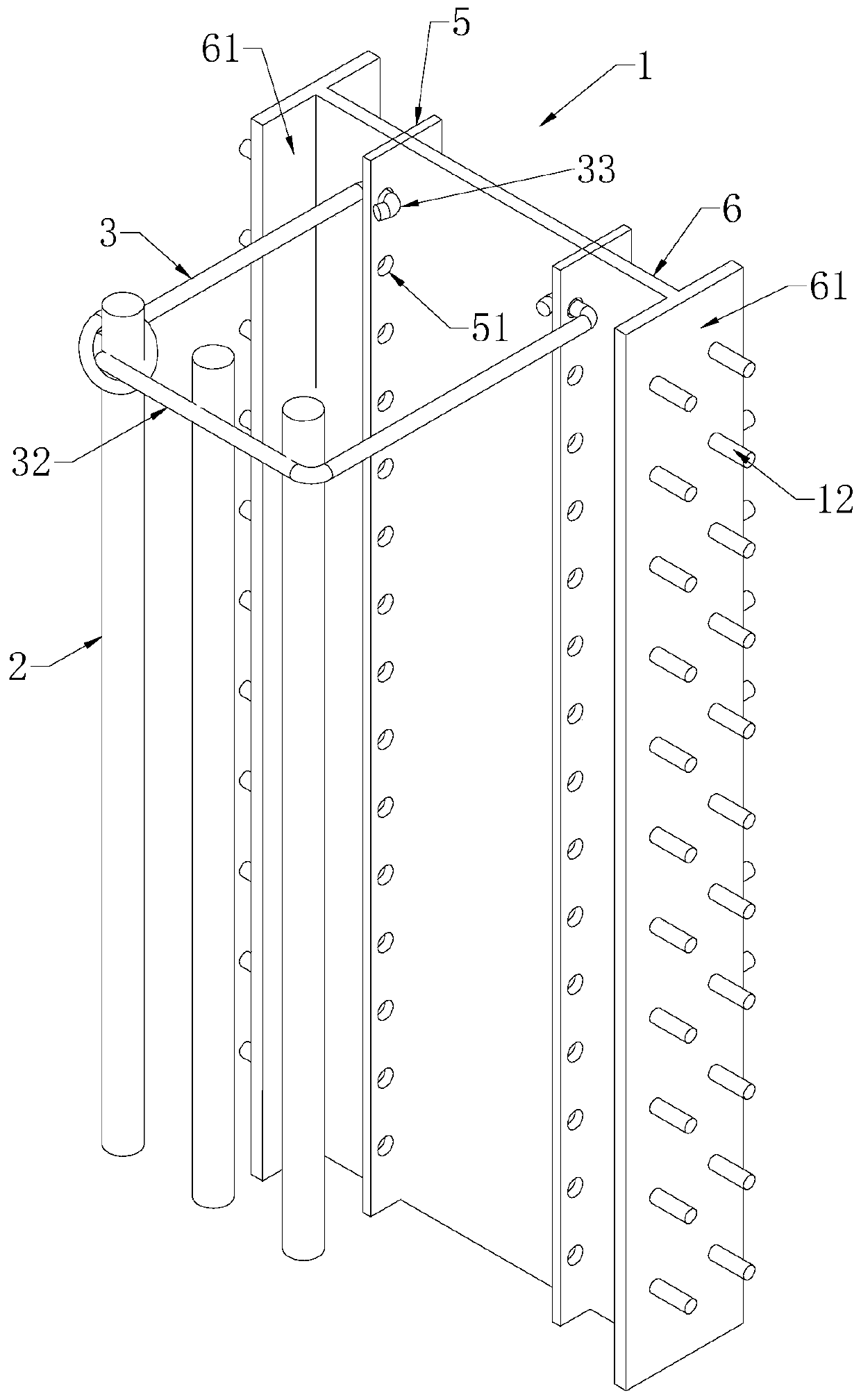
[0045] Such as image 3 As shown, a steel concrete structural column and stirrup connection structure, the difference from the first embodiment is: in this embodiment, the steel column 1 of the H-shaped steel is used; the H-shaped steel includes a second web 6 , both ends of the second web 6 are integrally formed or welded and fixed with a first end plate 61, and the first end plate 61 is perpendicular to the second web 6; on the side. The stirrup connecting plate 5 is welded and fixed on the two outer surfaces of the second web 6 , and the stirrup connecting plate 5 is welded and fixed on any one of the outer surfaces of the second web 6 along the position of one-third of its width direction .

Embodiment 3

[0047] Such as Figure 4 As shown, a steel concrete structural column and stirrup connection structure, the difference from Embodiment 1 is that: in this embodiment, the cross-shaped steel steel column 1 is used; the cross-shaped steel includes a cross-shaped structure The third web 7 can be formed by welding four third webs 7, or can be integrally formed to form a cross-shaped structure with four third webs 7, and the stirrup connecting plate 5 is welded and fixed to the third web 7. On the outer side of the three webs 7. The four ends of the cross-shaped structure formed by the third web 7 are welded and fixed with the second end plate 71, and the second end plate 71 is arranged perpendicular to the third web 7; the reinforcing nail 12 is welded and fixed on the second end plate 71 on the outer side.

[0048] The four third webs 7 are coplanar in pairs; the stirrup connecting plate 5 on a set of coplanar third webs 7 is set as the first stirrup connection group, and the ot...


PUM


Abstract

The invention discloses a connecting structure and construction method of steel ribs and hoops of a steel rib concrete structure column and relates to the technical field of steel rib concrete structure column construction. The BIM technology is used for establishing data models of profile steel rib columns, longitudinal reinforcing steel bars and the hoops, and meanwhile, the size and the positions of hoop connecting boards and the hole diameter and the forming positions of run-through holes are determined; and binding, buckling and fixing operation of the hoops, the profile steel rib columnsand the longitudinal reinforcing steel bars is finished on the site. In the hoop connection construction process of the profile steel concrete structure column, the longitudinal hoop connecting boards are welded to profile steel column webs, the hoops are buckled to the hoop connecting boards, web perforation and hoop welding construction are not needed, construction operation efficiency can be improved, the profile steel web section loss ratio can be reduced, hoop connection reliability can be guaranteed, the profile steel stress performance is improved, meanwhile, cost can be saved, a construction period can be shortened, and construction operation difficulty and construction personnel labor intensity are reduced.

Description

technical field [0001] The invention relates to the technical field of construction of a steel-reinforced concrete structural column, in particular to a connection structure of a steel frame and a stirrup of a steel-reinforced concrete structural column and a construction method thereof. Background technique [0002] In recent years, with the increasing number of high-rise and super high-rise buildings in China, reinforced concrete structures have been fully utilized and developed. However, in the traditional perforation and welding construction methods used in some steel concrete structural column stirrups, there are problems such as long construction time, many welding times, and heavy workload, which reduces construction efficiency and increases construction costs, and cannot meet the construction needs of the project. . [0003] The existing authorized announcement number is the Chinese patent of CN208168164U, which discloses the connection structure of the stirrups in ...

Claims


Application Information

Patent Timeline
IPC IPC(8): E04C3/34E04C5/06
CPCE04C3/34E04C5/0609
Inventor 嵇雪飞沈礼鹏沈培刘森维鲍芳琳钟启勇游佳陆夏
Owner THE FIRST CONSTR CO LTD OF CHINA CONSTR FIRST GRP
Why Eureka
Try Eureka