Method for remediation of contaminated soil and groundwater

A technology for polluted soil and groundwater, applied in the restoration of polluted soil, etc., can solve the problems of time-consuming and labor-consuming, slow migration, poor heat transfer effect, etc., and achieve the effect of shortening repair time, low construction cost, and concentrated reaction

Active Publication Date: 2021-12-21
CHINA PETROLEUM & CHEM CORP +1
View PDF10 Cites 0 Cited by
  • Summary
  • Abstract
  • Description
  • Claims
  • Application Information

AI Technical Summary

Problems solved by technology

CN103447291B discloses a method for strengthening gas-phase extraction and restoration of chlorobenzene-contaminated soil. The method includes adopting a plurality of heating extractors, condensing units, gas-liquid separators and vacuum pumps arranged in an equilateral triangle or a square, etc., in a short period of time. The remediation effect of chlorobenzene-contaminated soil is obvious, and the removal rate of pollutants is high, but the effect is easily affected by soil properties, etc. (for example, high soil viscosity, poor heat transfer effect)
CN102513347A discloses a method for treating polluted soil with in-situ thermal intensification combined with soil gas phase extraction technology. The method forms a certain form of heating well in the polluted area, deploys heater components in the heating well, and installs casings. The medium is filled with a catalyst to accelerate the pyrolysis of pollutants into simple small molecular substances; this method has a good treatment effect on pollutants, but the cost of the extraction device is high and it is difficult to popularize
In addition, since volatile and semi-volatile organic compounds are often difficult to dissolve in water and migrate slowly with groundwater, using PRB or extraction treatment technology directly downstream of the polluted area is not only time-consuming and labor-intensive, but also cannot fundamentally solve the pollution problem in the polluted area

Method used


Image

  • Method for remediation of contaminated soil and groundwater
  • Method for remediation of contaminated soil and groundwater

Examples


Embodiment approach

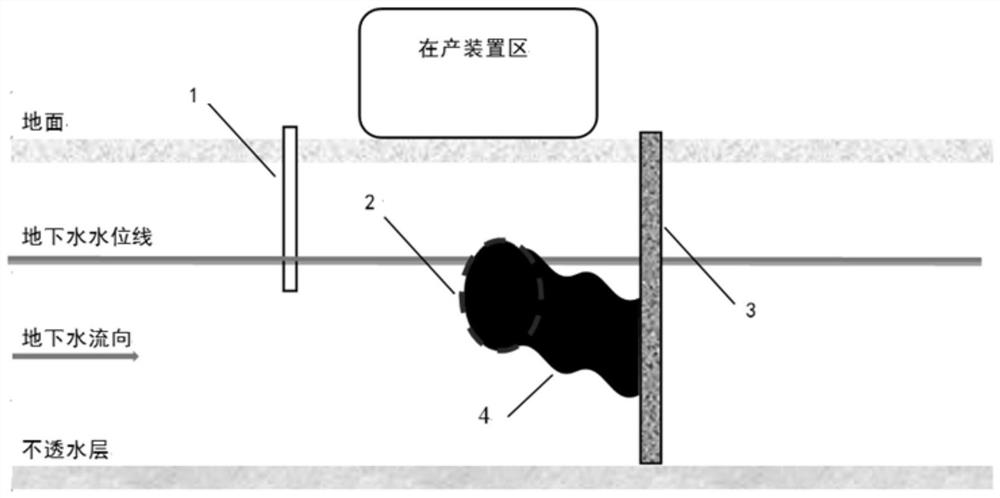
[0032] In the present invention, the injection well is built upstream of the groundwater in the polluted area, and is used to inject the surfactant slurry into the groundwater, so that the surfactant migrates into the polluted area along with the groundwater. When constructing the injection well, the depth of the well should be dug below the groundwater level. The present invention has no special limitation on the specific construction method and specifications of the injection well, which can be selected with reference to the prior art. According to one embodiment, the injection well has a diameter of 5-10 cm.

[0033] In the present invention, the pollutants in the contaminated area comprise volatile and / semi-volatile organic compounds. Specific examples of the pollutants include, but are not limited to, one or more of diesel, gasoline, benzene, toluene, di-n-octyl phthalate, and benzo(a)pyrene.

[0034] In the present invention, the surfactant may be a nonionic surfactant...

Embodiment 1

[0059] Diesel leakage from a buried pipeline at a gas station caused pollution. Before implementing this method, the total petroleum hydrocarbon (C10-C40) content in the soil in the polluted area was 20034 mg / kg, which exceeded the screening value for the second-class land in GB36600-2018 4500mg / kg, the benzene content of groundwater is 963μg / L, exceeding the conventional index limit of 120μg / L for Class IV water in GB / T14848-2017. The total petroleum hydrocarbon (C10-C40) content in the soil at the intermittent reaction wall was 8832 mg / kg, and the benzene content in the groundwater was 478 μg / L.

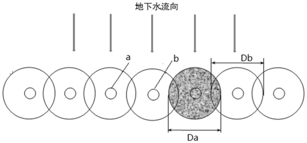
[0060] Build an injection well upstream of the groundwater in the polluted area. The diameter of the injection well is 5cm. A row of injection holes is constructed in the downstream of the groundwater in the polluted area perpendicular to the ground and groundwater flow. The diameter of the injection hole is 5cm. The construction between the holes The distance is 1m, the filling pi...

Embodiment 2

[0064] A leak occurred in the buried pipeline of a sewage pool, which caused the sewage containing dioctyl phthalate to seep into the ground. Before implementing this method, the content of dioctyl phthalate in the soil in the polluted area was 7498 mg / kg, exceeding GB36600-2018 stipulates that the screening value of Class II land use is 2812 mg / kg, and the content of di-n-octyl phthalate in groundwater is 669 μg / L, exceeding the unconventional index limit of 300 μg / L for Class IV water in GB / T14848-2017 . The content of dioctyl phthalate in the soil at the intermittent reaction wall was 5537 mg / kg, and the content of dioctyl phthalate in the groundwater was 492 μg / L.

[0065] Build an injection well upstream of the groundwater in the polluted area. The diameter of the injection well is 10cm. A row of injection holes is constructed in the downstream of the groundwater in the polluted area perpendicular to the ground and groundwater flow. The diameter of the injection hole is 5...


PUM


Abstract

The invention relates to the technical field of soil remediation, in particular to a method for remediating polluted soil and groundwater. The method comprises: 1) constructing an injection well upstream of the groundwater in the polluted area, and constructing a discontinuous reaction wall downstream of the groundwater in the polluted area, wherein the pollutants in the polluted area include volatile and / or semi-volatile organic compounds ; 2) Inject surfactant slurry into the injection well, so that the surfactant migrates to the polluted area under the action of groundwater to contact the pollutants therein, and the obtained oil-water mixture flows to the discontinuous reaction wall, where Under the barrier of the impermeable wall area, enter the permeable reaction area for reaction. The method of the invention can effectively remove volatile and semi-volatile organic compounds in polluted soil and underground water, and is also particularly suitable for repairing sites where excavation, extraction and injection operations cannot be performed above the polluted area.

Description

technical field [0001] The invention relates to the technical field of soil remediation, in particular to a method for remediating polluted soil and groundwater. Background technique [0002] The soil environment is one of the basic elements of the ecosystem, and the basis for the survival and development of human beings and organisms. With the development of my country's industrialization process, environmental pollution accidents and human health damage incidents occur from time to time. At present, volatile and semi-volatile organic pollutants have become the most common and prominent types of pollutants in the soil of industrial sites. Especially sudden environmental pollution accidents, such as oil storage tank leaks, oil pipeline ruptures, gasoline and diesel spills, etc. will cause varying degrees of pollution to soil and groundwater, and further bring greater harm to human health in the site. harm. [0003] The remediation methods for volatile and semi-volatile or...

Claims


Application Information

Patent Timeline
Patent Type & Authority Patents(China)
IPC IPC(8): B09C1/00B09C1/08
CPCB09C1/002B09C1/08B09C2101/00
Inventor 李博伟王岽骆宝进
Owner CHINA PETROLEUM & CHEM CORP
Why Eureka
Try Eureka