Rotary blowing clamping head for film coating of inner wall of light emitting diode (LED) lamp tube

A technology of LED lamp tube and wall coating film, applied in the direction of coating, device for coating liquid on the surface, pretreatment surface, etc., can solve the problems of stability affecting product quality, shaking of lamp tube, uneven thickness of coating film, etc. , to achieve the effect of stabilizing product quality, designing scientifically, and improving product quality

Inactive Publication Date: 2020-05-12
湖北如日电气股份有限公司
View PDF0 Cites 2 Cited by
  • Summary
  • Abstract
  • Description
  • Claims
  • Application Information

AI Technical Summary

Problems solved by technology

[0002] In the production process of LED lamp tubes, the inner wall coating process is involved. The production method is to spray the coating glue on the inner wall, insert it into the chuck around the equipment disc at the same time, and blow hot air inward through rotation to achieve the drying of the inner wall coating film. The wall is fixed, but the rotating chuck of the existing equipment cannot fix the lamp tube, causing the lamp tube to shake seriously when rotating, making the lamp tube prone to deflection, resulting in uneven heating of the coating film on the inner wall of the LED lamp tube, forming a coating film Uneven thickness directly affects the stability of product quality

Method used


Image

  • Rotary blowing clamping head for film coating of inner wall of light emitting diode (LED) lamp tube
  • Rotary blowing clamping head for film coating of inner wall of light emitting diode (LED) lamp tube
  • Rotary blowing clamping head for film coating of inner wall of light emitting diode (LED) lamp tube

Examples


Embodiment Construction

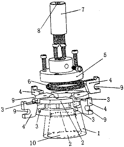
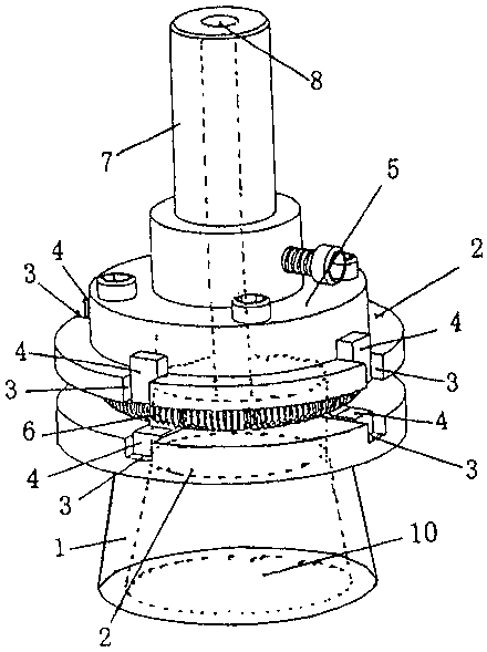
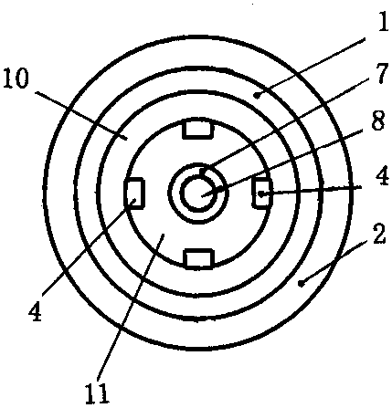
[0013] figure 1 , 2 , shown in 3 and 4: the conical revolving seat 1 that can be inserted into the lamp tube head 12 from the trumpet-shaped opening 10 below is connected with an integrated flange seat 2, and the conical revolving seat is distributed around the flange seat 2 1. There are several chutes 3 connected to the upper pipe head socket 10. Several chute 3s are respectively equipped with sliding claws 4 that can be snapped into the chute 3 and expose the tail end at the pipe head socket 11. Several sliding claws 4 pass through the ring Shaped extension spring 6 is tensioned and positioned in the chute 3, a bolt-fixed flange plate 5 is arranged above the flange seat 2, and a blowing nozzle 7 is screwed on the top of the flange plate 5, and the middle hole 8 of the blowing nozzle 7 is connected to the The lamp holder socket 11 in the conical revolving seat 1 below penetrates through. The annular tension spring 6 is clamped in the slots 9 of several sliding claws 4, form...


PUM


Abstract

The invention provides a rotary blowing clamping head for the film coating of the inner wall of a light emitting diode (LED) lamp tube. An integral flange seat is connected above a conical rotation seat capable of inserting a lamp tube head from a bottom trumpet-shaped opening; a plurality of sliding chutes which communicate with a top tube head insertion hole in the conical rotation seat are distributed around the flange seat; the plurality of sliding chutes are independently provided with a sliding claw which can be clamped into the chutes, and the tail end of each sliding claw is exposed from the tube head insertion hole; the plurality of sliding claws are tensioned through a circular ring shaped tension spring to be positioned in the sliding chutes; a flange plate in bolt fixing is arranged above the flange seat; a blowing nozzle is rotatably installed above the flange plate; and the middle hole of the blowing nozzle and a lamp head insertion hole in the bottom conical rotation seat are through. During utilization, the LED lamp tube head is sheathed into the whole of the device, and the plurality of sliding claws expand to the periphery to tension a top tube. Due to top and bottom vertical positioning, air can be inwards blown through the blowing nozzle, and therefore, a coated film is even and consistent.

Description

technical field [0001] The invention relates to a device for coating film of an LED lamp tube, in particular to a rotary blowing chuck for coating the film on the inner wall of the LED lamp tube. Background technique [0002] In the production process of LED lamp tubes, the inner wall coating process is involved. The production method is to spray the coating glue on the inner wall, insert it into the chuck around the equipment disc at the same time, and blow hot air inward through rotation to achieve the drying of the inner wall coating film. The wall is fixed, but the rotating chuck of the existing equipment cannot fix the lamp tube, causing the lamp tube to shake seriously when rotating, making the lamp tube prone to deflection, resulting in uneven heating of the coating film on the inner wall of the LED lamp tube, forming a coating film Uneven thickness directly affects the stability of product quality. Contents of the invention [0003] The purpose of the present inve...

Claims


Application Information

Patent Timeline
IPC IPC(8): B05B13/02B05D3/04
CPCB05B13/0207B05B13/0221B05D3/0413
Inventor 马安华
Owner 湖北如日电气股份有限公司
Why Eureka
Try Eureka