
An exhaust pollutant monitoring and purification device

A technology for purifying devices and pollutants, used in gas treatment, chemical instruments and methods, separation methods, etc., can solve the problems of high device complexity, high manufacturing, installation and use costs, vehicle exhaust gas treatment devices and exhaust flues. The exhaust gas treatment device does not meet the application requirements and other problems to achieve the effect of reducing costs

Active Publication Date: 2022-04-08
FAW JIEFANG AUTOMOTIVE CO
View PDF10 Cites 0 Cited by
  • Summary
  • Abstract
  • Description
  • Claims
  • Application Information

AI Technical Summary

Problems solved by technology

[0010] The disadvantages of the existing exhaust gas treatment devices for vehicles are that the exhaust gas treatment capacity is relatively weak, the system back pressure is high, and it cannot meet the treatment requirements of the full-type diesel engine test on the bench, and it does not have the ability of human-computer interaction
The disadvantage of the existing exhaust flue tail gas treatment device is that the device is highly complex, suitable for treating continuous high-concentration and large-flow tail gas, and the cost of manufacturing, installation and use is too high
[0011] Therefore, according to the exhaust characteristics of the diesel engine test bench, the vehicle exhaust gas treatment device and the exhaust flue gas treatment device do not meet the application requirements, and new devices need to be developed to realize the exhaust pollutant monitoring and purification functions of the diesel engine test bench

Method used


Image

  • An exhaust pollutant monitoring and purification device
  • An exhaust pollutant monitoring and purification device
  • An exhaust pollutant monitoring and purification device

Examples


Embodiment Construction

[0050] The present invention will be further described in detail below in conjunction with the accompanying drawings and embodiments. It should be understood that the specific embodiments described here are only used to explain the present invention, but not to limit the present invention. In addition, it should be noted that, for the convenience of description, only some structures related to the present invention are shown in the drawings but not all structures.

[0051] In the description of the present invention, unless otherwise clearly specified and limited, the terms "connected", "connected" and "fixed" should be understood in a broad sense, for example, it can be a fixed connection, a detachable connection, or an integrated ; It can be a mechanical connection or an electrical connection; it can be a direct connection or an indirect connection through an intermediary, and it can be the internal communication of two components or the interaction relationship between two ...


PUM


Abstract

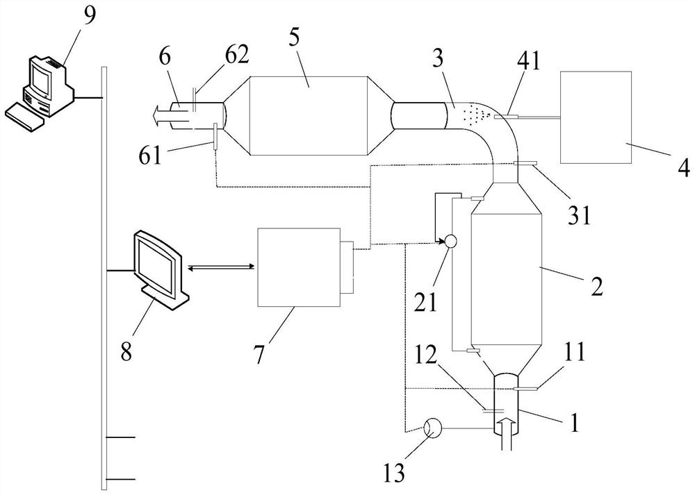
The invention belongs to the technical field of diesel engine tail gas treatment devices, and discloses an exhaust pollutant monitoring and purification device, which includes a first pipeline, a first catalytic converter, a second pipeline, a second catalytic converter, a third pipeline, a process ECU, and an HMI devices and master devices. The present invention aims at the characteristics of the diesel engine thermal test bench, arranges the exhaust purification device on the exhaust branch pipe of each bench of the diesel engine laboratory, adopts the mode of centralized control and distributed implementation, and is flexible according to the actual workload of the laboratory. Control the working status of each group of exhaust purification devices, and reduce the cost of pollutant control on the premise of meeting the requirements of industrial pollutant discharge regulations.

Description

technical field [0001] The invention relates to the technical field of diesel engine tail gas treatment devices, in particular to an exhaust pollutant monitoring and purification device. Background technique [0002] The diesel engine test runs through the entire diesel engine R&D and production process. During the test period, the environmental pollution problems caused by the exhaust emissions of the diesel engine bench also arise. According to the requirements of relevant regulations, it is necessary to monitor the amount of pollutants in the flue through the bench after-treatment device. [0003] The diesel engine hot test bench has the following characteristics: [0004] 1. Multiple benches share one exhaust flue. According to the different usage rates of the benches, the exhaust volume in the flue and the concentration of pollutants vary widely; [0005] 2. According to different test conditions, the exhaust frequency in the flue is also different. If it is a durabil...

Claims


Application Information

Patent Timeline
Patent Type & Authority Patents(China)
IPC IPC(8): B01D53/94B01D53/56B01D53/62B01D53/72B01D53/46B01D46/00
CPCB01D53/9459B01D53/9431B01D53/944B01D53/9418B01D53/9495B01D46/0027B01D46/00B01D2258/012
Inventor 王伏龚笑舞王毅明陆召振秦琳琳刘文辉唐立群靳越峰
Owner FAW JIEFANG AUTOMOTIVE CO
Learn More