Drying wardrobe
A technology for wardrobes and drying areas, applied in wardrobes, household clothes dryers, cabinets, etc., can solve the problems of multiple indoor spaces, difficult to popularize, and increase costs, and achieve enhanced safety performance, small footprint, and small footprint Effect
- Summary
- Abstract
- Description
- Claims
- Application Information
AI Technical Summary
Problems solved by technology
Method used
Image
Examples
Embodiment 1
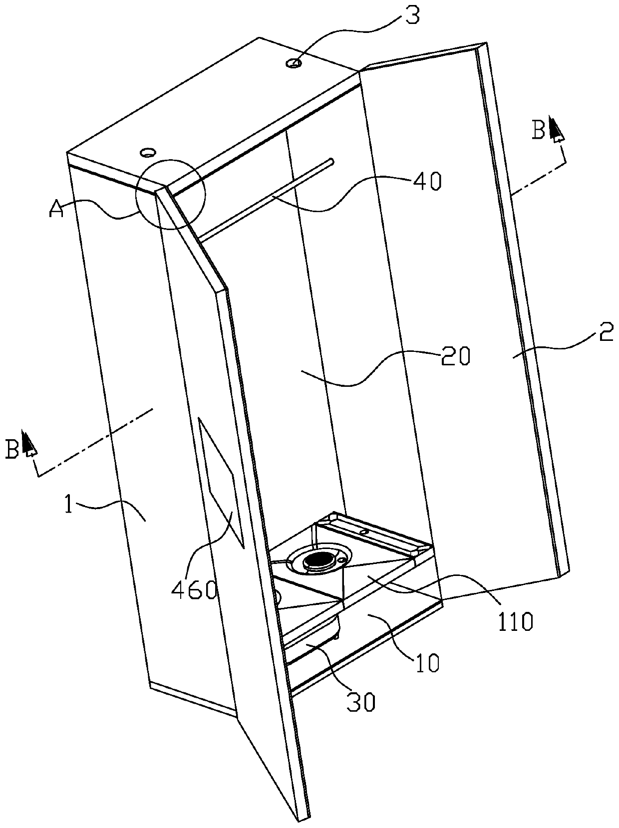
[0032] Figure 1 ~ Figure 4A drying wardrobe according to an embodiment of the present invention is schematically shown. The drying closet can be set in the hotel or hotel room to add drying function to the ordinary storage closet. Customers can dry the wet clothes in the room. The limitation of services can also avoid the inconvenience caused by sending and washing clothes. The drying wardrobe includes a cabinet body 1 and a cabinet door 2, the bottom of the cabinet body 1 is a heating zone 10, and a heater 30 is provided to provide hot air to the drying wardrobe. Above the heating zone 10 is a drying zone 20 , and the drying zone 20 is provided with a clothes rail 40 on which clothes to be dried are hung.
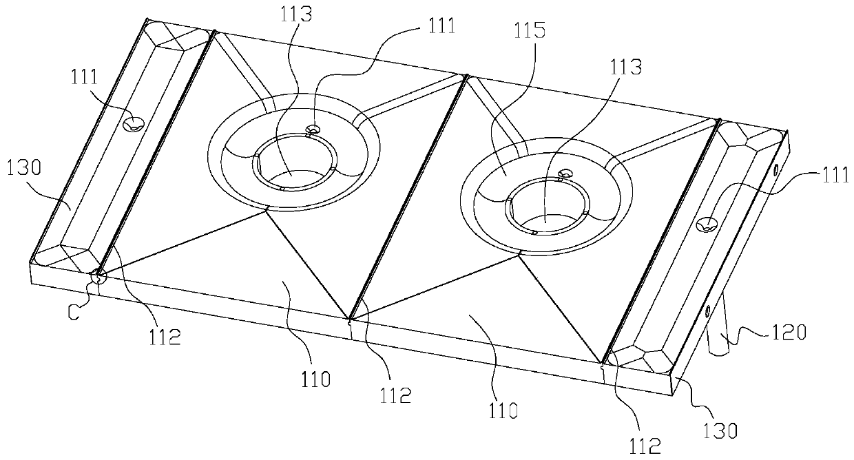
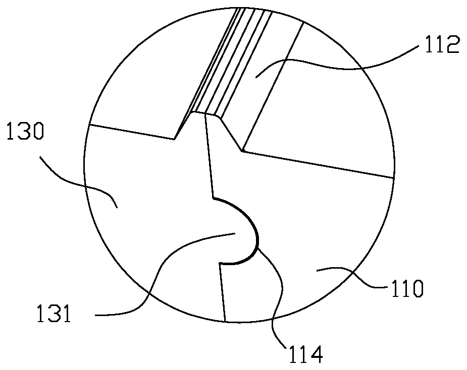
[0033] A water leakage structure is provided between the heating zone 10 and the drying zone 20 . like Figure 2 ~ Figure 4 As shown, the leaking structure includes a leaking board 110, the left and right edges of the leaking board 110 are provided with waterproof edg...
Embodiment 2
[0057] Figure 15 and Figure 16 A drying wardrobe according to another embodiment of the present invention is schematically shown. The difference with Example 1 is:
[0058] The air deflector is conical, and the conical air deflector is fixed on the through hole 113 of the water leakage plate 110, and the conical air deflector is made of waterproof and corrosion-resistant PVC material. The conical wind deflector includes a circular panel 210 at the top and a curved wind deflector 220 connected to the panel 210. Three legs 221 are uniformly arranged on the curved wind deflector 220, and the whole is an inverted cone structure. The through hole 113 is provided with 3 small holes, and the 3 legs 221 can be embedded in the small holes, so as to fix the conical wind deflector. The three supporting feet 221 are evenly distributed, which can ensure that the conical air deflector is evenly stressed, enhance stability, and prevent the conical air deflector from moving or toppling. ...
PUM
 Abstract
Description
Claims
Application Information
 - R&D Engineer
- R&D Manager
- IP Professional
- Industry Leading Data Capabilities
- Powerful AI technology
- Patent DNA Extraction
Browse by: Latest US Patents, China's latest patents, Technical Efficacy Thesaurus, Application Domain, Technology Topic, Popular Technical Reports.
© 2024 PatSnap. All rights reserved.Legal|Privacy policy|Modern Slavery Act Transparency Statement|Sitemap|About US| Contact US: help@patsnap.com


