Driving main machine of electric lifting type clothes hanger

A lift-type, driving motor technology, which is applied in the direction of electric components, clockwork mechanisms, electrical components, etc., can solve the problems of the time lag of the driving motor stopping work, the consumption of wire ropes, etc.

Pending Publication Date: 2020-05-08
黄山易森机电科技有限公司
View PDF2 Cites 6 Cited by
  • Summary
  • Abstract
  • Description
  • Claims
  • Application Information

AI Technical Summary

Problems solved by technology

[0008] The disadvantage of this limit mechanism is that the limit method is to trigger the limit switch after the clothes-horse reaches the upper limit or the lower limit position, and finally the drive motor will stop working; before the drive motor stops working, the wire rope is loose. , It takes a certain amount of time to move the pulley, which causes the drive motor to stop working and there is a time lag

Method used


Image

  • Driving main machine of electric lifting type clothes hanger
  • Driving main machine of electric lifting type clothes hanger
  • Driving main machine of electric lifting type clothes hanger

Examples


Embodiment 1

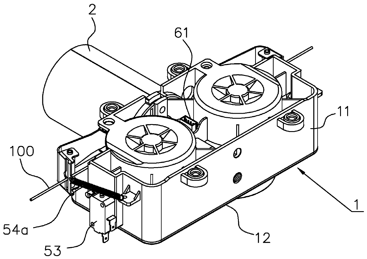
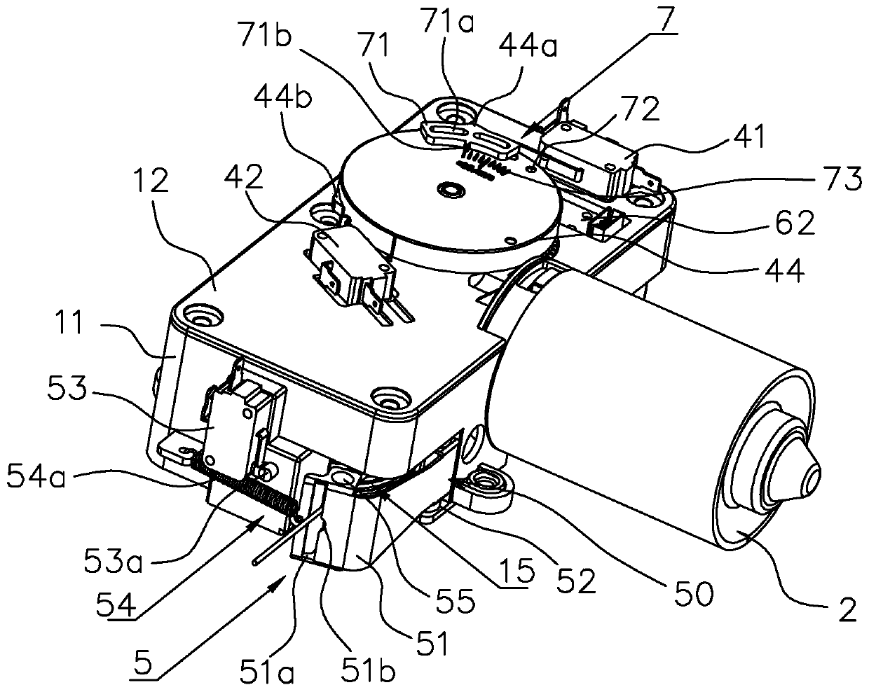
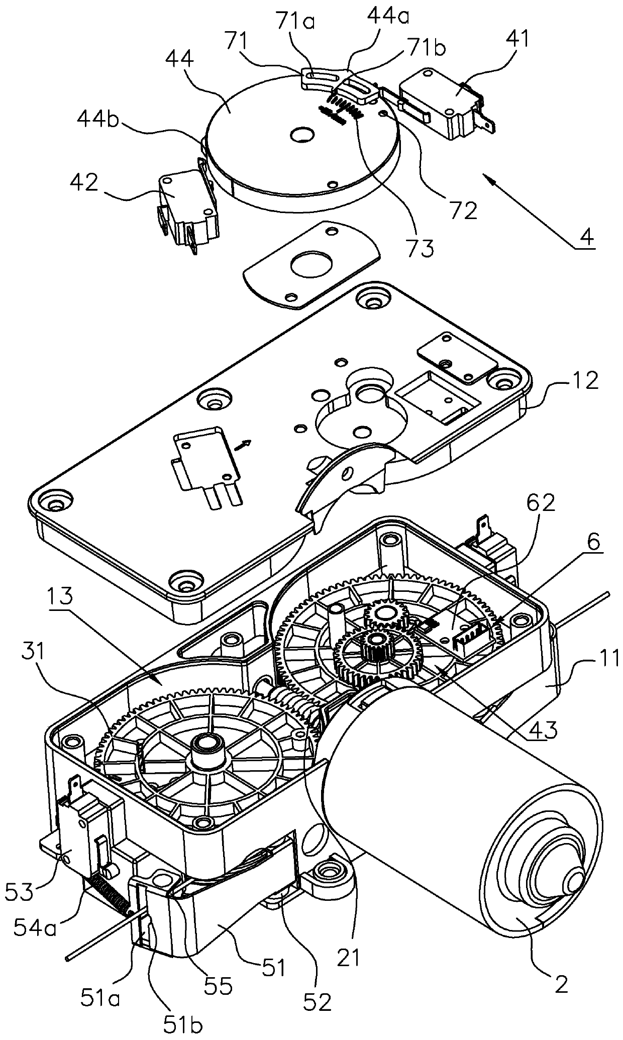
[0050] Such as figure 1 , figure 2 and image 3 As shown, the driving host of an electric lifting clothes drying rack in this embodiment includes a machine box 1, and the machine box 1 is composed of a box body 11 and a box cover 12, both of which are fixedly connected by bolts.

[0051] Two accommodating spaces 13 are symmetrically arranged in the box body 11, each accommodating space 13 is equipped with a reel 3, the central axis of the reel 3 is connected to the machine box 1 in rotation, and each reel 3 all have the worm gear 31 that is positioned at one end of reel 3.

[0052] One side of the box body 11 is fixedly installed with a drive motor 2 electrically connected to the electric control mechanism (not shown), the power shaft of the drive motor 2 is connected with the worm screw 21 arranged in the box body 11, and the The worm 21 meshes with the two worm wheels 31 respectively, and the driving motor 2 simultaneously drives the two reels 3 to rotate.

[0053] Such...


PUM


Abstract

The invention discloses a driving main machine of an electric lifting type clothes hanger. The main machine comprises a machine box, two symmetrically arranged wire winding wheels are arranged in themachine box, each wire winding wheel is provided with a worm wheel positioned at one end of the wire winding wheel, a lifting traction wire is wound on each wire winding wheel, a driving motor is arranged on the machine box, a worm located between the two worm wheels is connected to a power shaft of the driving motor, the worm meshes with the two worm wheels, the driving motor is electrically connected with an electric control mechanism, and the electric control mechanism is connected with a acquisition unit for acquiring signals of the number of rotation turns of the worm and / or signals of the number of rotation turns of the winding wheel. The power shaft of the driving motor and the wire winding wheel are in a linkage relation, rotate synchronously and are directly associated with the driving motor, so that signals acquired by the signal acquisition unit can be fed back to the electric control mechanism in real time, the electric control mechanism can control the driving motor timelyand quickly, and aging hysteresis does not exist.

Description

technical field [0001] The invention belongs to the technical field of electric clothes drying racks, and in particular relates to a driving host of electric lifting clothes drying racks. Background technique [0002] The electric lifting clothes rack is an intelligent furniture that many families will be equipped with. It not only eliminates the inconvenience caused by manual lifting, but also gives the clothes rack more additional functions. [0003] In the electric lifting clothes drying rack, the lifting of the clothes drying rod is realized by a lifting control device. There are two kinds of common lifting control devices. One is as shown in the Chinese utility model patent with the publication number CN207053319U, which includes a motor, a control circuit module for controlling the operation of the motor and a deceleration mechanism. The transmission assembly inside, the motor is installed on the reduction box, the motor shaft of the motor extends into the reduction b...

Claims


Application Information

Patent Timeline
Patent Type & Authority Applications(China)
IPC IPC(8): B66D1/12B66D1/14B66D1/48B66D1/54B66D1/56B66D1/60H02K7/10H02K7/14
CPCB66D1/12B66D1/14B66D1/485B66D1/54B66D1/56B66D1/60H02K7/10H02K7/14
Inventor 林修兴
Owner 黄山易森机电科技有限公司
Why Eureka
Try Eureka