Numerically-controlled lathe based on mechanical-electrical integration

A numerical control lathe and electromechanical technology, applied in the field of numerical control lathes, can solve the problems of poor adaptability of shaft-shaped workpieces or cylindrical workpieces, and achieve the effects of simple structure, good processing effect and high flexibility

Inactive Publication Date: 2020-05-08
马新国
View PDF8 Cites 0 Cited by
  • Summary
  • Abstract
  • Description
  • Claims
  • Application Information

AI Technical Summary

Problems solved by technology

For this reason, an object of the present invention is to provide a kind of numerical control lathe based on electromechanical integration, mainly solve the problem that the existing numerical control lathe is not strong adaptability to shaft type workpiece or cylinder type workpiece

Method used


Image

  • Numerically-controlled lathe based on mechanical-electrical integration
  • Numerically-controlled lathe based on mechanical-electrical integration
  • Numerically-controlled lathe based on mechanical-electrical integration

Examples


Embodiment 1

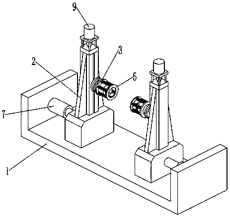
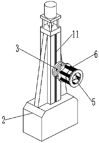
[0031] Such as Figure 8 Shown is a clamping device of a CNC lathe clutch in the prior art, including a base 1, the left and right sides of the top of the base 1 are respectively fixedly connected with a first support column 2 and a second support column 3, the first support column The left side surface of 2 is fixedly connected with a fixed frame 4, and the inside of the fixed frame 4 is fixedly connected with a fixed plate 5, and a slide bar 6 is fixedly connected between the fixed plate 5 and the inner wall of the fixed frame 4, and the left surface of the fixed plate 5 is fixedly connected There is a first sleeve 7, the end of the first sleeve 7 away from the fixed plate 5 is sleeved with a threaded rod 8, the surface of the fixed frame 4 is fixedly sleeved with a bearing 9, the inner ring of the bearing 9 is fixedly sleeved with the threaded rod 8, The end of the threaded rod 8 away from the first sleeve 7 runs through the bearing 9 and is fixedly connected with the turnt...

Embodiment 2

[0043] Embodiment 2 is a further improvement to Embodiment 1.

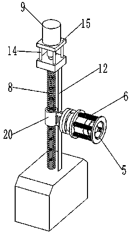
[0044] In practical application, considering that debris generated during workpiece processing may enter the chute 11 and adhere to the screw rod 8, affecting the transmission of the screw rod 8, an elastic belt 12 that can cover the chute 11 is also provided here. Specifically, as image 3 and Figure 4 As shown, the slide block 20 divides the chute 11 into the first chute 11 and the second chute 11, the first chute 11 and the second chute 11 are all provided with a vertical elastic band 12, the elastic band 12 One vertical end is fixedly connected with the slider 20, and the other vertical end of the elastic band 12 is fixedly connected with the slide table 2. The elastic band 12 blocks the chute 11. Since the elastic band 12 is elastic, a large elastic deformation can occur , so the elastic band 12 will not occupy much space of the chute 11 .

[0045] Further, as Figure 4 As shown, the opposite vertical gr...


PUM


Abstract

The invention relates to a numerically-controlled lathe based on mechanical-electrical integration. The numerically-controlled lathe based on mechanical-electrical integration comprises a base, a sliding platform, a clamping head, a first driving mechanism and a second driving mechanism; the sliding platform is slidably installed on the base, the base is provided with the first driving mechanism,and the first driving mechanism is connected with the sliding platform and is suitable for driving the sliding platform to horizontally slide; the clamping head is slidably installed on the sliding platform, the sliding platform is provided with the second driving mechanism, and the second driving mechanism is connected with the clamping head and is suitable for driving the clamping head to vertically slide; the clamping head comprises an installing base, a top plate and springs, the installing base is provided with a clamping shaft horizontally extending, the clamping shaft is provided with multiple shaft sections of which the outer diameters are gradually decreased in the axial direction of the clamping shaft, the top plate is of an annular structure, the top plate and the clamping headare coaxially arranged, and the springs extending in the horizontal direction are fixedly connected between the installing base and the top plate; and when the springs are in a balanced state, the outer end face of the top plate is flush with the outer end face of the outermost-side shaft section of the clamping shaft.

Description

technical field [0001] The invention relates to the field of mechanical processing, in particular to a numerically controlled lathe based on electromechanical integration. Background technique [0002] CNC lathes, also known as CNC lathes, that is, computer numerical control lathes, are the most widely used and widely covered CNC machine tools in China, accounting for about 25% of the total number of CNC machine tools. CNC machine tools are mechatronic products that integrate many technologies such as machinery, electricity, hydraulic pressure, pneumatics, microelectronics and information. It is a machine tool with the advantages of high precision, high efficiency, high automation and high flexibility in machinery manufacturing equipment. The technical level of CNC machine tools and their percentages in the output and total ownership of metal cutting machine tools are one of the important indicators to measure a country's national economic development and the overall level ...

Claims


Application Information

Patent Timeline
Patent Type & Authority Applications(China)
IPC IPC(8): B23Q3/08B23Q1/25
CPCB23Q1/25B23Q3/082
Inventor 马新国
Owner 马新国
Why Eureka
Try Eureka