
Steel plate water cooling device

A water-cooling device and water-cooling technology, applied in the field of steel plate cooling, can solve the problems of high cooling investment cost, affecting heat exchange efficiency and quality, and taking away the real-time temperature of water-cooled rollers, etc.

Active Publication Date: 2020-05-08
合肥赛欧机械制造有限公司
View PDF5 Cites 0 Cited by
  • Summary
  • Abstract
  • Description
  • Claims
  • Application Information

AI Technical Summary

Problems solved by technology

[0002] During the casting process of the steel plate, it is necessary to dissipate heat and cool down in time. Most of the existing heat dissipation equipment are water-cooled heat exchange devices. These devices use the rotation of the water-cooled roller to perform heat exchange on the steel plate. , and the water circulation cooling cannot take away the real-time temperature on the water-cooled roller at a certain node. With the prolongation of the use time, the overall temperature of the water-cooled roller will gradually increase, which will greatly affect the subsequent cooling effect of the steel plate, and can only reduce the circulation The temperature of the water is improved, so the cooling input cost is high, and the water-cooled roller works at high temperature for a long time. Thermal corrosion will lead to a significant decrease in the service life of the water-cooled roller, which will easily lead to damage and scrap of the water-cooled roller, which indirectly affects the heat transfer efficiency and quality

Method used


Image

  • Steel plate water cooling device
  • Steel plate water cooling device
  • Steel plate water cooling device

Examples


Embodiment Construction

[0038] The technical solutions of the present invention will be further described below in conjunction with the accompanying drawings and through specific implementation methods.

[0039] Wherein, the accompanying drawings are only for illustrative purposes, showing only schematic diagrams, rather than physical drawings, and should not be construed as limitations on this patent; in order to better illustrate the embodiments of the present invention, some parts of the accompanying drawings will be omitted, Enlargement or reduction does not represent the size of the actual product; for those skilled in the art, it is understandable that certain known structures and their descriptions in the drawings may be omitted.

[0040] In the drawings of the embodiments of the present invention, the same or similar symbols correspond to the same or similar components; , "inner", "outer" and other indicated orientations or positional relationships are based on the orientations or positional ...


PUM


Abstract

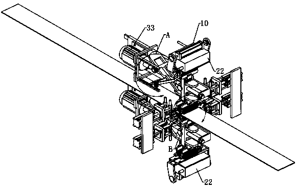
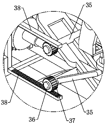
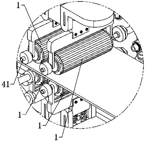
The invention relates to the field of steel plate cooling, in particular to a steel plate water cooling device which comprises water cooling cylinders, a water inlet mechanism, a circulating mechanismand a cooling bin. The water inlet mechanism and the circulating mechanism are symmetrically arranged, a transfer plate is arranged between the water inlet mechanism and the circulating mechanism, the number of the water cooling cylinders is two, and the water cooling cylinders can be rotatably arranged on one side of the transfer plate; one of the two water cooling cylinders can always be opposite to the cooling bin, and the other of the two water cooling cylinders is located between the water inlet mechanism and the circulating mechanism, and the two ends of the corresponding water coolingcylinder can communicate with the water inlet mechanism and the circulating mechanism. An air flow cavity and a cooling cavity are arranged in the cooling bin, the cooling cavity is always opposite toone water cooling cylinder, a transmission structure is always opposite to the air flow cavity is arranged at one end of the corresponding water cooling cylinder, the water cooling cylinders are elastically connected with the transfer plate, a displacement mechanism is further arranged on the side of the transfer plate, the displacement mechanism is in transmission connection with the two water cooling cylinders and can force the two water cooling cylinders to move backwards, and a high-pressure spray head and a cooling spray head are arranged in the air flow cavity and the cooling bin correspondingly. The service life of the water cooling cylinders can be prolonged, and the heat exchange effect is uniform.

Description

technical field [0001] The invention relates to the field of steel plate cooling, in particular to a steel plate water cooling device. Background technique [0002] During the casting process of the steel plate, it is necessary to dissipate heat and cool down in time. Most of the existing heat dissipation equipment are water-cooled heat exchange devices. These devices use the rotation of the water-cooled roller to perform heat exchange on the steel plate. , and the water circulation cooling cannot take away the real-time temperature on the water-cooled roller at a certain node. With the prolongation of the use time, the overall temperature of the water-cooled roller will gradually increase, which will greatly affect the subsequent cooling effect of the steel plate, and can only reduce the circulation The temperature of the water is improved, so the cooling input cost is high, and the water-cooled roller works at high temperature for a long time. Thermal corrosion will lead t...

Claims


Application Information

Patent Timeline
Patent Type & Authority Applications(China)
IPC IPC(8): B22D30/00
CPCB22D30/00
Inventor 陈东辉
Owner 合肥赛欧机械制造有限公司
Learn More