Transceiver integrated all-optical ultrasonic transducer device and preparation method thereof
An ultrasonic transducer, an integrated technology, applied in the direction of fluid using vibration, etc., can solve the problems of increasing the complexity of photoacoustic signal processing, increasing the spatial resolution of imaging, unfavorable device miniaturization, etc., to achieve process feasibility, Conducive to acoustic imaging and compact structure
- Summary
- Abstract
- Description
- Claims
- Application Information
AI Technical Summary
Problems solved by technology
Method used
Image
Examples
Embodiment 1
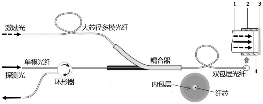
[0041] figure 1 A schematic diagram of the transceiver-integrated all-optical transducer device in Embodiment 1 is shown.
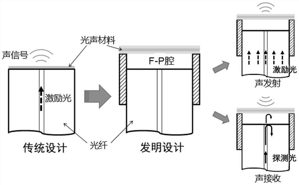
[0042] Such as figure 1 As shown, the transceiver integrated all-optical ultrasonic transducer device includes: a double-clad optical fiber 1, a structured base 2, and a suspended membrane 3; the inner wall of the structured base 2 has the same shape as the side of the cylinder, and can The outer wall of the fiber sleeve (such as ceramic sleeve or metal sleeve) that fixes the double-clad optical fiber 1 fits (the fiber sleeve is in figure 1 not shown). Wherein, the cladding of the double-clad fiber 1 is used to transmit excitation light, and the core is used to transmit probe light; the structured base 2 is used to fix the double-clad fiber and the suspension film, and is connected with The exit end faces jointly define the cavity length of the F-P cavity (the exit end face of the double-clad fiber is perpendicular to the optical axis, and the distance...
Embodiment 2
[0076] This embodiment is substantially the same as Embodiment 1, except that the sandwich structure of PDMS—candle soot carbonnanoparticles (CSPs)—PDMS does not require an additional composite glass.
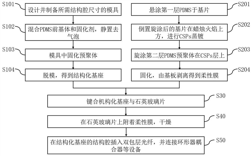
[0077] At this time, steps S30 and S40 of the preparation method of Example 1 need to be adjusted as follows as a whole, and other steps S10, S201, S202, S203, and S50 remain unchanged, and step S204 does not need to be performed at the same time:
[0078] S30, bonded structured base and flexible membrane:
[0079] Specifically, the second PDMS layer of the substrate in S203 is bonded to the open cavity surface of the base to obtain a joint body 1 .
[0080] At this time, the sealing of the structural cavity is realized by an irreversible bonding process between the PDMS colloid (corresponding to the structured base 2 ) and the PDMS colloid (corresponding to the suspension film 3 ). The bonding process and precautions are the same as in Example 1.
[0081] S40, separating the...
Embodiment 3
[0083] This embodiment is substantially the same as Embodiment 2. The sandwich structure of PDMS—candle soot carbonnanoparticles (CSPs)—PDMS is directly bonded to the PDMS surface (i.e., the open cavity surface) of the structured base, except that the sandwich The outside of the type structure is additionally provided with quartz glass, which can make the device structure cavity obtain higher rigidity, so as to meet the application occasions that require other requirements for mechanical strength.
[0084] At this time, compared with Example 2, the preparation method remains unchanged in steps S10, S20, S30, and S50:
[0085] The substrate mentioned in S20 needs to be preferably a thin quartz glass sheet, such as a quartz glass layer with a thickness of 50-200um (the specific material, thickness, and characteristics can be changed according to the application scenario).
[0086] S40 does not need to be performed, and the combination 1 obtained in S30 is equivalent to the combi...
PUM
 Abstract
Description
Claims
Application Information
 - R&D
- Intellectual Property
- Life Sciences
- Materials
- Tech Scout
- Unparalleled Data Quality
- Higher Quality Content
- 60% Fewer Hallucinations
Browse by: Latest US Patents, China's latest patents, Technical Efficacy Thesaurus, Application Domain, Technology Topic, Popular Technical Reports.
© 2025 PatSnap. All rights reserved.Legal|Privacy policy|Modern Slavery Act Transparency Statement|Sitemap|About US| Contact US: help@patsnap.com


