Wind power generation device based on piezoelectric principle and implementation method thereof

A wind power generation and piezoelectric technology, applied in piezoelectric effect/electrostrictive or magnetostrictive motors, photovoltaic power generation, generators/motors, etc., can solve windmill noise and visual pollution, visual pollution, increase land occupation Area and other issues to achieve the effect of reducing the center of gravity and failure rate, avoiding visual pollution, and reducing the footprint

Inactive Publication Date: 2020-05-05
SHANDONG JIAOTONG UNIV
View PDF0 Cites 0 Cited by
  • Summary
  • Abstract
  • Description
  • Claims
  • Application Information

AI Technical Summary

Problems solved by technology

In the context of the increasing installed capacity of wind power generation, many shortcomings have also been exposed. First, the noise and visual pollution of the windmill. Because the speed-up device of the windmill adopts mechanical transmission, a lot of noise will be generated during operation, and the structure of the windmill is simple. , the volume is huge, and the expansion of installed capacity inevitably brings visual pollution; secondly, in order to increase the power generation of a single machine, the blades of windmills are getting bigger and bigger, which undoubtedly greatly increases the occupied area; thirdly, the center of gravity of windmills is high, and the blades in the wind Medium and high-speed rotation causes poor dynamic stability of windmills, and windmill accidents occur from time to time; the latest research shows that windmills will bring serious ecological pollution during operation, resulting in fewer birds; in addition, windmills also have high costs, Difficulty in maintenance and other issues

Method used


Image

  • Wind power generation device based on piezoelectric principle and implementation method thereof
  • Wind power generation device based on piezoelectric principle and implementation method thereof
  • Wind power generation device based on piezoelectric principle and implementation method thereof

Examples


Embodiment Construction

[0021] The technical solutions of the present invention will be further described below through the accompanying drawings and embodiments.

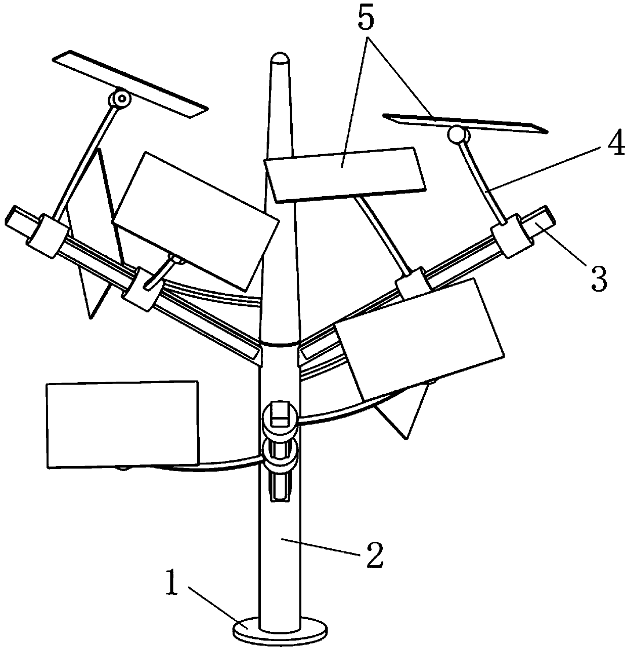
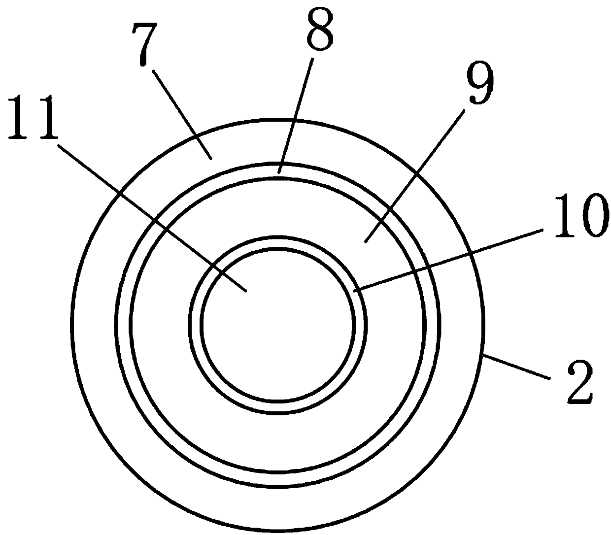
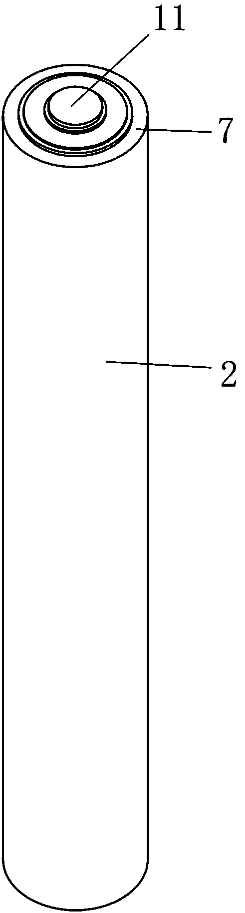
[0022] control figure 1 , figure 2 , a wind power generation device based on the principle of piezoelectricity, comprising a base 1 and a piezoelectric backbone 2, the base 1 is fixedly installed on a horizontal plane, the piezoelectric backbone 2 is fixedly installed on the base 1, and the piezoelectric backbone A protective layer 7 is wrapped on the outermost side, and a piezoelectric layer 9 , an electrode layer and a support body 11 are contained inside.

[0023] control figure 1 , figure 2 , image 3 , the first electrode layer 8 is installed between the inner side of the protective layer 7 and the outer side of the piezoelectric layer 9, the second electrode layer 10 is installed on the inner side of the piezoelectric layer 9, and the innermost measurement of the piezoelectric backbone 2 is a support body 11 , the material of...


PUM


Abstract

The invention discloses a wind power generation device based on a piezoelectric principle and an implementation method thereof. The wind power generation device based on the piezoelectric principle comprises a base and a piezoelectric trunk, wherein the piezoelectric trunk is fixedly installed on the base, the outermost side of the piezoelectric trunk is wrapped by a protective layer, and the piezoelectric trunk internally comprises a piezoelectric layer; a first electrode layer is mounted between the inner side of the protective layer and the outer side of the piezoelectric layer; a second electrode layer is mounted on the inner side of the piezoelectric layer; the innermost side of the piezoelectric trunk is a support body; the protective layer is made of a polymer insulating material; the first electrode layer and the second electrode layer are made of copper; the piezoelectric layer is made of single crystal piezoelectric materials; the supporting body is made of various materials;branches are installed at the upper end of the piezoelectric trunk, and photovoltaic panels are installed on the branches; and under the action of natural wind, the piezoelectric trunk deforms, the piezoelectric layer generates voltage between the two electrode layers, and the voltage can be led out through a circuit. The wind power generation device is attractive in appearance, does not destroyecology, and has the advantages of being stable in operation process, free of noise and the like.

Description

technical field [0001] The invention relates to the field of wind power generation, in particular to a wind power generation device based on the piezoelectric principle and a realization method thereof. Background technique [0002] With the continuous reduction of fossil fuels, wind energy, as a renewable energy source, has become more and more important in the process of human energy acquisition. At present, wind power generation is realized on the basis of Faraday's electromagnetic induction principle, that is, wind energy is converted into rotating mechanical energy through windmills, and electric energy is generated by cutting magnetic force lines after speeding up. In the context of the increasing installed capacity of wind power generation, many shortcomings have also been exposed. First, the noise and visual pollution of the windmill. Because the speed-up device of the windmill adopts mechanical transmission, a lot of noise will be generated during operation, and the...

Claims


Application Information

Patent Timeline
Patent Type & Authority Applications(China)
IPC IPC(8): H02N2/18H02S10/12
CPCH02N2/185H02S10/12Y02E10/50
Inventor 张林孔曼曼李学永
Owner SHANDONG JIAOTONG UNIV
Why Eureka
Try Eureka