


Quick Research
Generate reliable direction feasibility study reports for your R&D in just a few steps.

Technical Q&A
Discover and master advanced knowledge NOW. Basics, ideas, possibilities, all at once.

Find Solutions
As an expert in R&D theories, this can generate solutions to your technical problems instantly.

Evaluate Feasibility
Analyze your overall solution with one click, know your potential R&D risks in advance.

Monitor Landscape
Get weekly tech updates, stay abreast of the latest tech innovations and key insights.
Rotor, motor and compressor
A rotor and rotor core technology, applied in the fields of rotors, motors and compressors, can solve problems such as the poor performance of the magnetic isolation bridge and the vibration of the motor, and achieve the effects of reducing noise and vibration, reducing magnetic flux leakage, and modifying the direction of the magnetic circuit Effect
- Summary
- Abstract
- Description
- Claims
- Application Information
AI Technical Summary
Problems solved by technology
Method used
Image


Examples
Embodiment 1
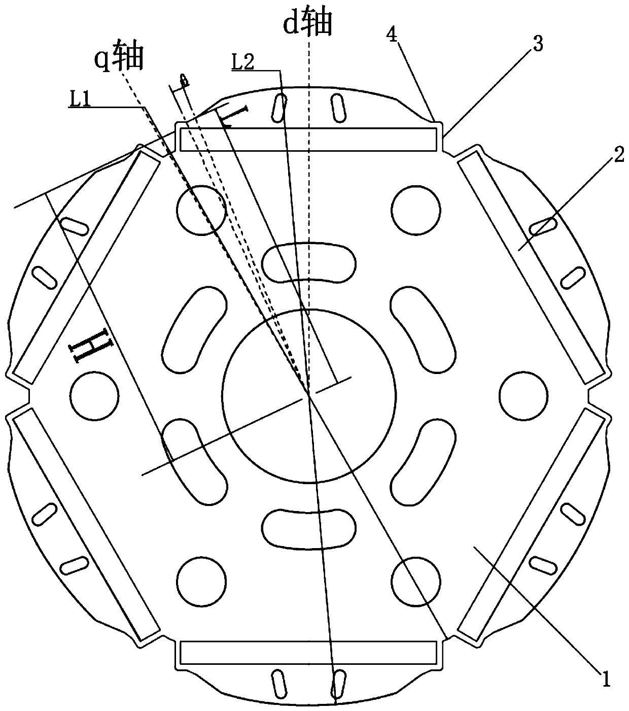
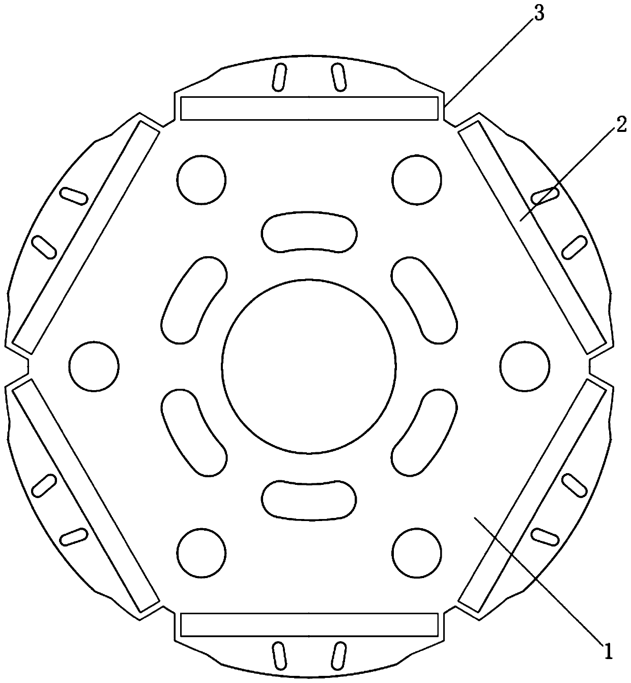
[0030] like figure 1 As shown, the cylindrical surface of the rotor core is formed with a plurality of concentrically arranged arc surfaces, including a first arc surface intersecting with the q axis and a second arc surface intersecting with the d axis. The radius L1 of the first arc surface, the radius L2 of the second arc surface, and the maximum distance H between the magnetic steel slot and the center of the rotor iron core satisfy L2>H>L1, so that the rotor iron core is located at two lengths of the magnetic steel slot along the length direction. A first magnetic isolation bridge is formed at the ends respectively.
[0031] In addition to the first magnetic isolation bridge, the rotor iron core is respectively formed with a second magnetic isolation bridge on the outer sides of both ends of the magnetic steel slot along the width direction. The second magnetic isolation bridge is connected to the first magnetic isolation bridge, and the two sections of the magnetic isol...
Embodiment 2
[0035] The rotor core described in Embodiment 2 is different from Embodiment 1 in that the center distance L of the second magnetic isolation bridge close to one end of the second arc surface, and the radius L2 of the second arc surface, satisfy 0.96≤L / L2≤0.98. At the same time, from the end of the second magnetic isolation bridge close to the second arc surface to the second arc surface, the center distance of each point on the outer tangent edge of the rotor within the angle θ range is ≤ L, and 1°≤θ≤8°.
PUM
 Abstract
Description
Claims
Application Information
 - R&D Engineer
- R&D Manager
- IP Professional
- Industry Leading Data Capabilities
- Powerful AI technology
- Patent DNA Extraction
Browse by: Latest US Patents, China's latest patents, Technical Efficacy Thesaurus, Application Domain, Technology Topic, Popular Technical Reports.
© 2024 PatSnap. All rights reserved.Legal|Privacy policy|Modern Slavery Act Transparency Statement|Sitemap|About US| Contact US: help@patsnap.com