
A plate pure shear experimental loading device

A loading device and pure shearing technology, applied in measuring devices, using stable shear force to test material strength, analyzing materials, etc., can solve the problem of affecting the pure shear stress value, the degree of influence cannot be quantitatively described, and cannot be guaranteed. Pure shear stress state and other problems, to achieve the effect of simple implementation process

Active Publication Date: 2022-02-15
王渡初
View PDF7 Cites 0 Cited by
  • Summary
  • Abstract
  • Description
  • Claims
  • Application Information

AI Technical Summary

Problems solved by technology

Therefore, with the increase of shear deformation, additional tensile stress will appear in the deformation area, and the degree of influence of this type of tensile stress cannot be described quantitatively, which not only affects the determination of the value of pure shear stress, but also involves Until the accurate determination of the shear strain value, it is impossible to guarantee that the material in this area is always in a state of pure shear stress during the whole loading process, which is a problem coexisting with the existing plate shear test methods

Method used


Image

  • A plate pure shear experimental loading device
  • A plate pure shear experimental loading device
  • A plate pure shear experimental loading device

Examples


Embodiment 1

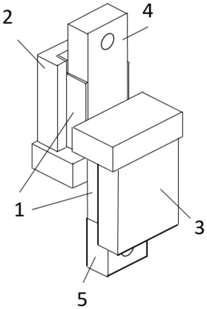
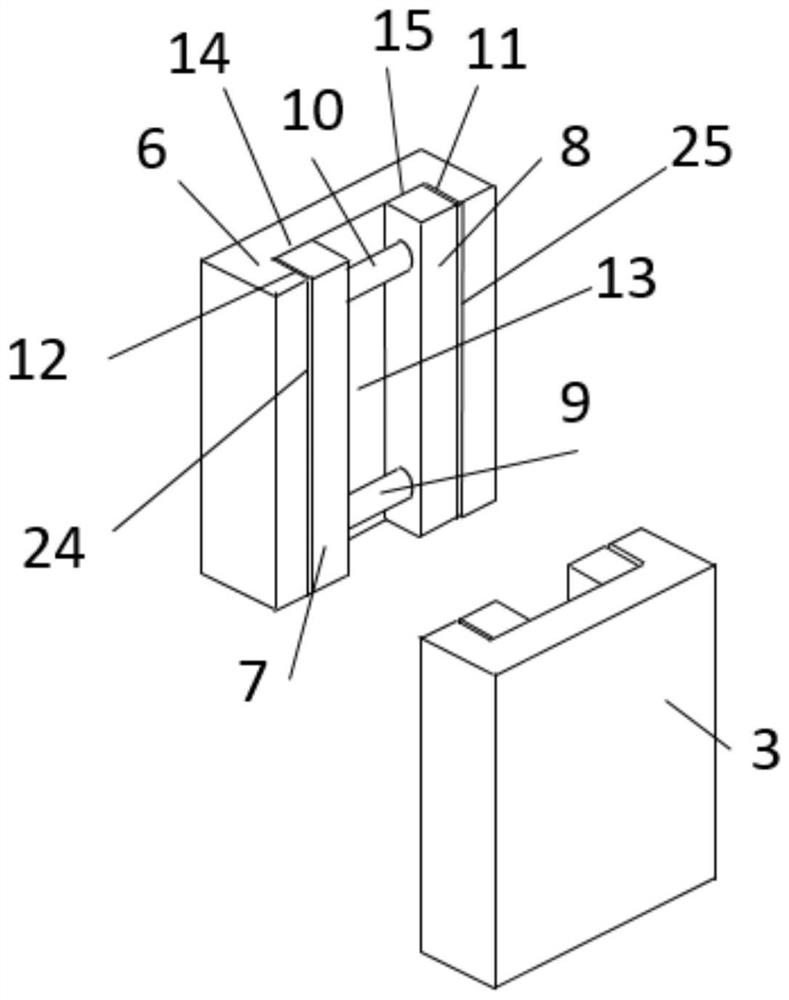
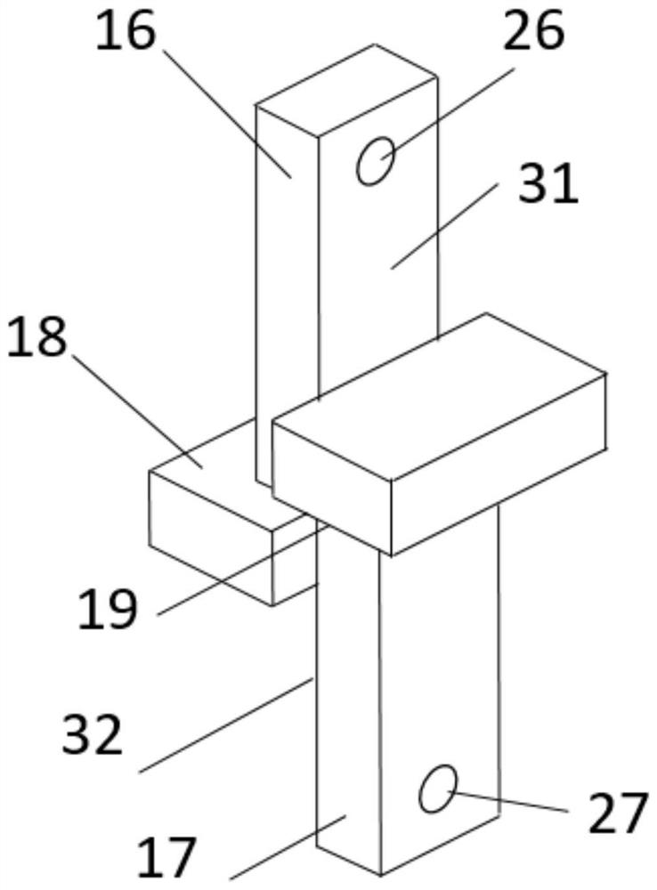
[0028] see Figure 1-4, this embodiment provides a loading device for plate pure shear experiments, including a first connection assembly 2 and a second connection assembly 3, the first connection assembly 2 and the second connection assembly 3 have the same structure and are relatively misplaced. The first connecting component 2 and the second connecting component 3 are equipped with a first moving bar 7 and a second moving bar 8 opposite to each other. The first connecting component 2 and the second connecting component 3 are equipped with a plate 1 to be tested. The first moving bar 7 and the second moving bar 8 are connected through the first locking bolt system 10 and the second locking bolt system 9, and the inside of the first connecting assembly 2 is provided with a U-shaped structure Locate the inner surface 13, the left locking surface 24 of the first moving bar and the right locking surface 25 of the second moving bar, the positioning of the plate end positioning su...

Embodiment 2

[0037] On the basis of Example 1, for the connection of the plate 1 to be tested with the first connection assembly 2 and the second connection assembly 3, first, a pair of plate 1 to be tested is placed between the first connection assembly 2 and the second connection assembly 3 In the opening, since the first connecting component 2 and the second connecting component 3 operate in the same manner, here only the fixing process of the first connecting component 2 and the panel 1 to be tested is described as an example.

[0038] The plate 1 to be tested is placed in the first connection assembly 2, so that its positioning surface 22 is close to the positioning inner surface 13 of the first connection assembly 2, and then the first moving bar 7 and the second moving bar 8 are adjusted so that The right inner surface 11 of the first connection assembly, the left inner surface 12 of the first connection assembly is close to the inner surface 20 of the upper half of the plate 1 to be...


PUM

PropertyMeasurementUnit
thicknessaaaaaaaaaa
lengthaaaaaaaaaa

Abstract

The invention provides a plate pure shear experimental loading device, belonging to the technical field of plate mechanical performance testing, comprising a first connection component and a second connection component, the first connection component and the second connection component have the same structure and are relatively dislocated , the first connecting component and the second connecting component are equipped with a first moving bar and a second moving bar opposite to each other, and plates are arranged inside the first connecting component and the second connecting component, and the first moving bar The bolt and the second moving bar are connected through the first locking bolt system and the second locking bolt system. The implementation process of the invention is simple, no special equipment needs to be designed, and it can be completed with a conventional tensile testing machine; the invention makes the plate to be tested The shear force only occurs on a pair of fixed shear planes; the shear deformation also occurs on the fixed shear plane, and no plastic deformation occurs in other areas.

Description

technical field [0001] The invention belongs to the technical field of plate mechanical performance testing, in particular to a plate pure shear test loading device. Background technique [0002] In the automotive, aircraft and shipbuilding industries, sheet metal, especially rolled sheet metal, is used extensively. Products with different geometric shapes undergo different processing techniques, for example, the most commonly used stamping forming process, so that they can obtain the final formed structural shape. Plastically processed sheet metal parts play a key role in the quality of the overall product, for example, the overall quality of a car. [0003] In order to avoid failure phenomena such as wrinkling and cracking of the sheet during plastic processing, it is necessary to understand the mechanical properties of the sheet used, especially with the help of computer numerical simulation technology, to simulate the formability of the sheet during the forming process,...

Claims


Application Information

Patent Timeline
Patent Type & Authority Patents(China)
IPC IPC(8): G01N3/24
CPCG01N3/24G01N2203/0025G01N2203/0075G01N2203/0282
Inventor 胡卫龙王渡初
Owner 王渡初
Learn More