
fuel tank level sensor

An oil level sensor and oil level sensing technology, applied in the direction of float level indicator, etc., can solve the problems of low resolution, poor precision, and reduced precision of position signal.

Active Publication Date: 2021-05-04
赛卓电子科技(上海)股份有限公司
View PDF14 Cites 0 Cited by
  • Summary
  • Abstract
  • Description
  • Claims
  • Application Information

AI Technical Summary

Problems solved by technology

[0006] 1) The technical principle of the reed switch determines the characteristics of its single-point position detection. As the float (magnet) moves up and down, a reed switch can only detect one position of the float (magnet) at a time and output the switch signal. If If long-distance detection is required, multiple reed switches are required, which makes the resolution of the position signal very low and the accuracy is extremely poor;
[0007] 2) With the extension of the detection distance of the application end, the manufacturing cost of the oil level sensor is increasing continuously, and the current requirements for energy saving and emission reduction of automobiles are continuously increasing, and the detection of automobile oil level is particularly important. Accurate oil level measurement can reduce energy consumption. Therefore, in order to increase the accuracy of the sensor, the back-end single-chip microcomputer is required to perform linear correction processing, which also increases the difficulty of oil level detection;
[0008] 3) The demagnetization of the float (magnet) at high temperature and the detection distance from the reed switch will affect the switch point of the reed switch, resulting in a decrease in the accuracy of the position signal

Method used


Image

  • fuel tank level sensor
  • fuel tank level sensor
  • fuel tank level sensor

Examples


Embodiment Construction

[0040] The present invention will be described in detail below in conjunction with specific embodiments. The following examples will help those skilled in the art to further understand the present invention, but do not limit the present invention in any form. It should be noted that those skilled in the art can make several changes and improvements without departing from the concept of the present invention.

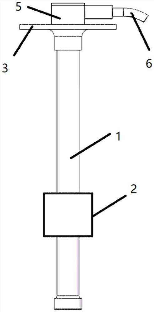
[0041] figure 1 It is a schematic diagram of the appearance of a general non-contact automotive fuel tank oil level sensor.

[0042] Such as figure 1 As shown, the non-contact automotive fuel tank oil level sensor includes a tubular sensor housing 1, a float 2 (usually a magnet) arranged outside the sensor housing 1, and a fixing seat 3 arranged at the end of one side of the sensor housing 1. , the top cover 5 and the outgoing signal line 6 arranged on the fixing base 3 .

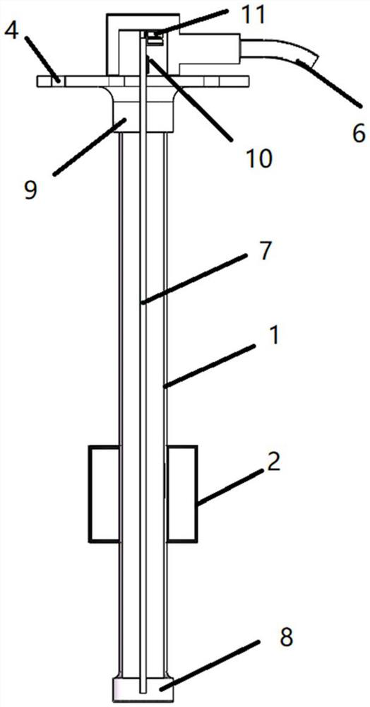
[0043] figure 2 It is the internal sectional view of the reed switch oil level sensor.

[0...


PUM


Abstract

The fuel tank oil level sensing mechanism and the sensor using the fuel tank oil level sensing mechanism of the present invention include a signal circuit module and a mobile module for mutual induction; the signal circuit module includes: a circuit board assembly; a processing circuit assembly, the processing circuit assembly is arranged in the circuit on the board component; the sensing component, the sensing component is arranged on the circuit board component, the sensing component is connected with the processing circuit component, and the sensing component and the mobile module sense each other; the sensing film, the sensing film is set on the circuit board component, and the sensing film covers the sensing component. The invention has high position signal accuracy and high resolution; low cost and simple structure; it ensures the stability of the position signal of the sensor in harsh working environments; the sensing film made of soft magnetic materials has low coercive force, low magnetic saturation density and high The characteristics of magnetic permeability, this kind of material can use the smallest external magnetic field and the fastest speed to achieve the maximum magnetization or magnetic saturation, and when the external magnetic field dissipates, this kind of material can demagnetize at the fastest speed.

Description

technical field [0001] The invention relates to a fuel tank oil level sensing mechanism and a sensor using the fuel tank oil level sensing mechanism. Background technique [0002] Automobile fuel tank oil level sensor is a measuring instrument tailored for the precise measurement of automobile fuel tank oil level. [0003] In the current existing technology, the oil (liquid) level sensor is divided into two types: contact induction and non-contact induction. The contact oil level sensor uses a sliding potentiometer as the basic detection element, which is driven by a float. Use an ohmmeter to detect its resistance value, so as to achieve the purpose of displaying the oil level. This type of contact oil level sensor is low in cost, but when the oil dirt covers the potentiometer, its resistance value will change, causing great errors, and even failure of function. Make this type of oil level sensor a very short-lived wearing part. [0004] Another type of non-contact oil lev...

Claims


Application Information

Patent Timeline
Patent Type & Authority Patents(China)
IPC IPC(8): G01F23/72G01F23/76
CPCG01F23/72G01F23/76
Inventor 陶骋戚宏亮宋红刚
Owner 赛卓电子科技(上海)股份有限公司
Learn More