
Complete upper inlet air burner

A burner, complete technology, applied in burners, gas fuel burners, combustion methods, etc., can solve the problems of airflow interference, poor gas adaptability, small combustion flame, etc., to achieve the effect of power and combustion stability

Pending Publication Date: 2020-05-05
陈毅
View PDF0 Cites 0 Cited by
  • Summary
  • Abstract
  • Description
  • Claims
  • Application Information

AI Technical Summary

Problems solved by technology

[0003] Most of the existing burners include a central fire cover and a main fire cover. The central fire cover and the main fire cover are independent parts. more complex
[0004] The center fire structure of the existing burner is an independent type, and the flame of the center fire hole is ejected to the periphery of the burner, which is easy to intersect with the outer ring fire of the burner, and it is easy to cause the phenomenon of non-flammable combustion. High CO emissions and low thermal efficiency
[0005] Some of the existing upward air-intake burners generally have small ejectors, which cannot meet the large-load ejection requirements, so the heat load is generally small, only about 3.5-4.0kW, and the combustion flame is small, which cannot reach Chinese food. stir fry demand
At the same time, because the injector is small, the adaptability to gas is poor, and the combustion stability is poor, so it has not been well promoted.
[0006] There is airflow interference between the primary air and the secondary air when the existing part of the complete upward air intake burner is working, there is a phenomenon of air grabbing, and the combustion stability is poor

Method used


Image

  • Complete upper inlet air burner
  • Complete upper inlet air burner
  • Complete upper inlet air burner

Examples


Embodiment Construction

[0057] The present invention will be described in further detail below in conjunction with the accompanying drawings and embodiments.

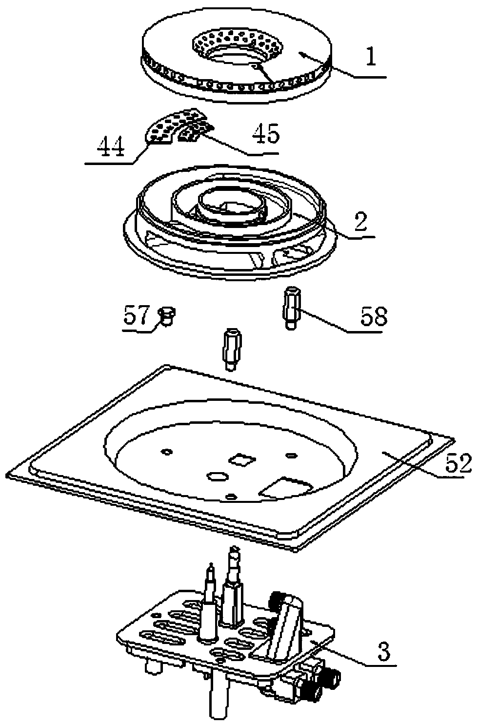
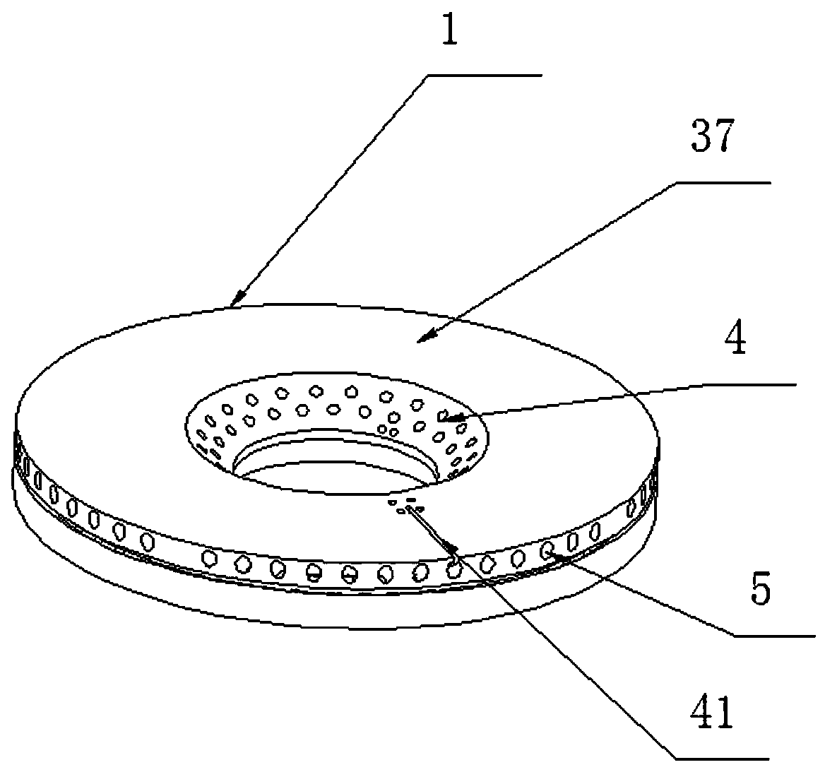
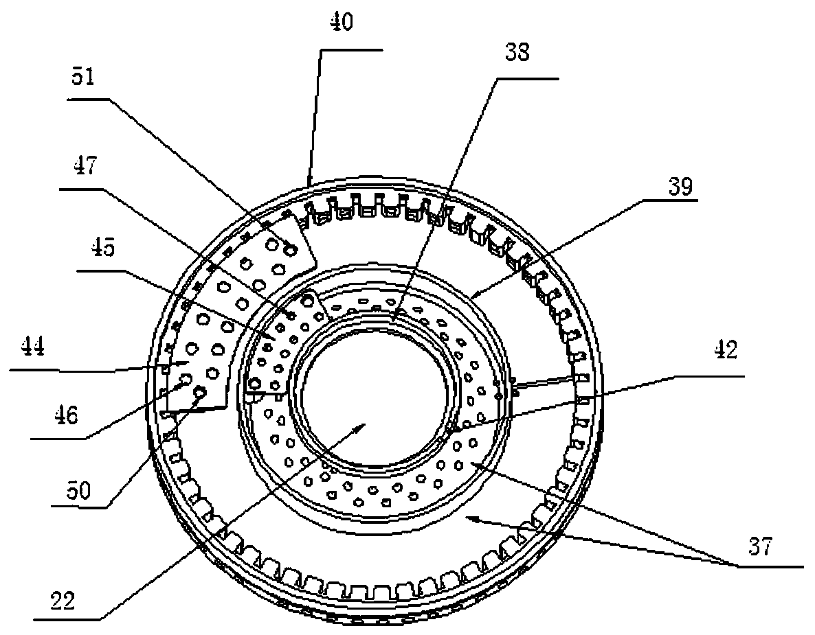
[0058] refer to Figure 1-Figure 14 , a completely upward air-intake burner, including an integrated fire cover 1, an integrated burner head 2 and a burner support 3, the integrated fire cover 1 is covered on the integrated burner head 2, and the integrated fire cover 1 is provided with a central fire outlet hole 4 and The main fire outlet 5, the integrated burner 2 is provided with a central fire mixing chamber 6 and a main fire mixing chamber 7, and the integrated burner 2 includes a burner partition 10, a central fire ejector 11 and a main fire ejector 12, The center fire ejector 11 is fixed on the upper surface of the burner partition 10, the main fire ejector 12 is fixed on the lower surface of the burner partition 10, the gas outlet 11B of the center fire ejector 11 is connected with the center fire mixing chamber 6 Connected, the gas o...


PUM


Abstract

The invention discloses a complete upper inlet air burner which comprises an integrated fire cover, an integrated furnace end and a burner support. The integrated fire cover covers the integrated furnace end; a central fire outlet and a main fire outlet is formed in the integrated fire cover; a central fire mixing cavity and a main fire mixing cavity are formed in the integrated furnace end; the integrated furnace end comprises a furnace end partition board, a central fire ejector and a main fire ejector; the central fire ejector is fixed on the upper surface of the furnace end partition board; the main fire ejector is fixed on the lower surface of the furnace end partition board; the air outlet end of the central fire ejector communicates with the central fire mixing cavity; the air outlet end of the main fire ejector communicates with the main fire mixing cavity; the central fire mixing cavity communicates with a central fire dividing cavity; the main fire mixing cavity communicateswith a main fire dividing cavity; the central fire dividing cavity communicates with a central fire outlet of the integrated fire cover; and the main fire dividing cavity communicates with a main fireoutlet of the integrated fire cover. The complete upper inlet air burner is compact in structure, excellent in ejecting capacity, and high in stability, burning power and working reliability.

Description

technical field [0001] The invention relates to a complete upward air-flow burner. Background technique [0002] At present, in the gas cooker and integrated stove industry, most of the burners use the bottom-inlet combustion technology. Although some are upward-inlet, they are based on the bottom-inlet burner, and the burner head is lifted. In order to realize the supply of secondary air from the top of the panel, but the supplement of primary air does not realize the upward air intake, so it cannot be called a complete upward air intake technology. And when the burner is applied to an ordinary gas stove, the cabinet door needs to be provided with ventilation holes; Both the size and the stability of the pull wire operating mechanism directly affect the working reliability of the burner. [0003] Most of the existing burners include a central fire cover and a main fire cover. The central fire cover and the main fire cover are independent parts. more complicated. [0004...

Claims


Application Information

Patent Timeline
Patent Type & Authority Applications(China)
IPC IPC(8): F23D14/04F23D14/64F23D14/82
CPCF23D14/04F23D14/64F23D14/82Y02B40/00
Inventor 陈毅陈明军
Owner 陈毅
Learn More