
Embossing plate precise positioning mechanism for synchronous alignment floor

A technology of precise positioning and embossing board, which is applied to cleaning methods using gas flow, decorative arts, painting tools, etc., can solve problems such as reducing the effect of floor embossing, using deflection of positioning mechanism, affecting positioning accuracy of positioning mechanism, etc. Achieve the effect of improving embossing effect, avoiding deflection and increasing positioning accuracy

Pending Publication Date: 2020-05-01
JIANGSU KENTIER WOOD
View PDF0 Cites 0 Cited by
  • Summary
  • Abstract
  • Description
  • Claims
  • Application Information

AI Technical Summary

Problems solved by technology

[0004] 1. It is generally difficult to achieve height adjustment and correction functions for traditional positioning mechanisms of this type, which can easily lead to deflection when the positioning mechanism is used;
[0005] 2. It is generally difficult to realize the offset indication function when the traditional positioning mechanism is used, which seriously affects the positioning accuracy of the positioning mechanism;
[0006] 3. The traditional positioning mechanism of this type rarely sets the processing work on the impurities attached to the floor surface, thus reducing the embossing effect of the positioning mechanism on the floor

Method used


Image

  • Embossing plate precise positioning mechanism for synchronous alignment floor
  • Embossing plate precise positioning mechanism for synchronous alignment floor
  • Embossing plate precise positioning mechanism for synchronous alignment floor

Examples


Embodiment Construction

[0024] The following will clearly and completely describe the technical solutions in the embodiments of the present invention with reference to the accompanying drawings in the embodiments of the present invention. Obviously, the described embodiments are only some, not all, embodiments of the present invention. Based on the embodiments of the present invention, all other embodiments obtained by persons of ordinary skill in the art without making creative efforts belong to the protection scope of the present invention.

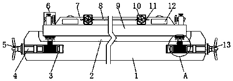
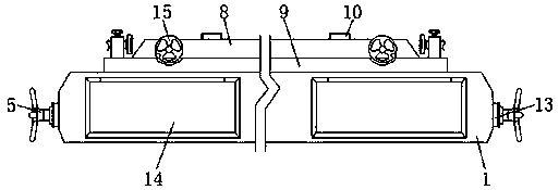
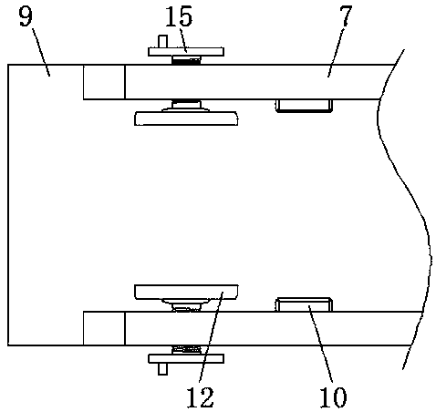
[0025] see Figure 1-5 , an embodiment provided by the present invention: a precise positioning mechanism for an embossed board of a synchronous floor, including a base 1, a placement cavity 2, an indicating mechanism 6, a correction support plate 9 and a turbine 17, and the center position of the top of the base 1 A placement cavity 2 is provided at the bottom of the placement cavity 2, and a correction groove 3 is provided at the corner of the base 1 below t...


PUM


Abstract

The invention discloses an embossing plate precise positioning mechanism for a synchronous alignment floor. The mechanism comprises a base, a placing cavity, indication mechanisms, a correction support plate and a turbine. The placing cavity is formed in the center position of the top end of the base, correction grooves are formed in the corners of the base below the placing cavity, the correctionsupport plate is arranged in the placing cavity, and correction frames are hinged to the corners of the bottom end of the correction support plate through hinge balls respectively. The indication mechanisms are fixed to the corners of the top end of the correction support plate, transverse plates are installed at the two ends of the correction support plate on the inner sides of the indication mechanisms, moving grooves are formed in the inner side walls of the transverse plates, the two ends in each moving groove are provided with micro fans, and fastening screws are in threaded connection with the outer walls of the transverse plates on the two sides of the moving grooves. The height adjusting and correction functions are achieved when the positioning mechanism is used, the deviation indication function is achieved when the positioning mechanism conducts positioning, and the embossing effect of the positioning mechanism on the floor is improved.

Description

technical field [0001] The invention relates to the technical field of floor positioning, in particular to a precise positioning mechanism for an embossed plate of a synchronously aligned floor. Background technique [0002] Floor, that is, the surface layer of the ground or floor of the house, the floor is generally divided into solid wood floor, solid wood composite floor, reinforced composite floor, synchronous flower floor, geothermal heating floor, plastic floor, anti-static floor, bamboo wood composite floor, etc. It is often necessary to use a precise positioning mechanism for synchronous embossing of floor tiles. [0003] There are many types of such positioning mechanisms on the market today, which can basically meet people's needs, but there are still some problems. The specific problems are as follows: [0004] 1. It is generally difficult to achieve height adjustment and correction functions for traditional positioning mechanisms of this type, which can easily l...

Claims


Application Information

Patent Timeline
Patent Type & Authority Applications(China)
IPC IPC(8): B44B5/00B44B5/02B08B5/02
CPCB44B5/0052B44B5/02B44B5/022B08B5/02B44B2700/12
Inventor 房轶群张军华
Owner JIANGSU KENTIER WOOD
Learn More