Cleaning device for sheet metal part production

A cleaning device and a technology for sheet metal parts, applied in the field of sheet metal processing, can solve problems such as the classification and collection of waste that cannot be cleaned, and achieve the effects of increasing the sandblasting reuse rate, improving the cleaning process, and improving the cleaning effect

Active Publication Date: 2020-05-01
ZHUZHOU HUAXIN PRECISION IND
View PDF9 Cites 5 Cited by
  • Summary
  • Abstract
  • Description
  • Claims
  • Application Information

AI Technical Summary

Problems solved by technology

[0004] Based on the technical problem that the current sheet metal parts cleaning device cannot classify and collect cleaning waste, the present invention proposes a cleaning device for sheet metal parts production

Method used


Image

  • Cleaning device for sheet metal part production
  • Cleaning device for sheet metal part production
  • Cleaning device for sheet metal part production

Examples


Embodiment 1

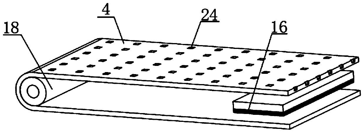
[0030] A cleaning device for sheet metal production, such as Figure 1-2 Shown, comprise main chassis 17,, the slide rail 10 that horizontal setting is connected with by bolt in the middle of the top inner wall of main chassis 17, the bottom inner wall of sliding track 10 is slidably connected with the suspension bar 11 that vertical setting is arranged, the both sides of main chassis 17 Both sides inner wall bottoms are all connected with the fixed base plate 23 that horizontally arranges by bolt, the top inner wall of fixed base plate 23 and the top of main frame 17 are sleeved with vertically arranged rotating central axis 7, and the circumference outer wall of rotating central axis 7 is covered. Connect with the cleaning brush 15 that is vertically arranged, the inner wall on both sides of the main frame 17 is connected with the sandblasting pipe 6 that is horizontally arranged by bolts, and the bottom between the two ends inner walls of the main frame 17 is sleeved with tw...

Embodiment 2

[0034] A cleaning device for sheet metal production, such as Figure 1-5Shown, one side inner wall top of main frame 17 is connected with the dust removal cabinet 25 that vertically arranges by bolt, and the top of dust removal cabinet 25 is equipped with the air intake grille 27 that horizontally arranges, between the top and the bottom of air intake grille 27 A vertically arranged air inlet 28 is installed between them, and the top entrance of the air inlet 28 is narrow, and one side of the dust removal cabinet 25 is provided with a first hole, and the first hole is sleeved with a fan barrel 26, and the fan barrel 26 A fan is socketed on the inner wall of the circumference, and the fan cylinder 26 is socketed on one side of the main chassis 17 .

[0035] In this embodiment, when in use, a vertical dust removal cabinet 25 is installed on the side inner wall of the main chassis 17, the dust removal cabinet 25 can absorb debris and dust generated by cleaning, and the top of the...


PUM


Abstract

The invention belongs to the technical field of sheet metal processing and particularly relates to a cleaning device for sheet metal part production. The cleaning device aims to solve the problems that cleaning waste cannot be well classified and collected by using an existing sheet metal part cleaning device. According to the scheme, the cleaning device comprises a main machine box, the middle portion of the inner wall of the top of the main machine box is connected with a horizontal sliding rail through bolts, a vertical suspension rod is slidably connected to the inner wall of the bottom ofthe sliding rail, the bottoms of the inner walls of the two sides of the main machine box are connected with horizontal fixed bottom plates through bolts, and the portions between the tops of the fixed bottom plates and the inner wall of the top of the main machine box are sleeved with vertical rotating middle shafts. According to the cleaning device for sheet metal part production, a dischargingbelt has the magnesium, debris generated by cleaning can be collected, scrap iron can be sucked, waste chips with no magnetism are directly discharged through a second discharging hopper, and magnetic iron sand is discharged from a first discharging hopper through a demagnetizing plate, so that the waste of the device is more convenient to classify and collect.

Description

technical field [0001] The invention relates to the technical field of sheet metal processing, in particular to a cleaning device for sheet metal production. Background technique [0002] Sheet metal parts are commonly used raw materials for metal crafts. During the production process of sheet metal parts, the surface is often corroded, and sandblasting cleaning is required. At present, many companies still use manual operations for cleaning sheet metal parts, which is less efficient. Moreover, during the cleaning process, sheet metal parts may be bent and worn, reducing the pass rate of finished products and increasing production costs. [0003] After retrieval, the Chinese patent authorization announcement number is CN208341219U patent, which discloses a sheet metal parts cleaning device, including a box body, a water tank, a spray device, a scrubbing device and a conveying device. The box body is fixedly connected to the water tank through a connecting piece. The top of ...

Claims


Application Information

Patent Timeline
Patent Type & Authority Applications(China)
IPC IPC(8): B08B1/04B08B3/02B08B13/00B08B15/04
CPCB08B3/02B08B13/00B08B15/04B08B1/32B08B1/12
Inventor 谢钧辉
Owner ZHUZHOU HUAXIN PRECISION IND
Why Eureka
Try Eureka