
Gluing device for continuous glue feeding of PCB

A technology of PCB board and gluing device, which is applied to devices and coatings that apply liquid to the surface, can solve problems such as interruption of gluing work and inability to operate continuously, and achieve the effect of stable gluing and quality assurance.

Inactive Publication Date: 2020-05-01
南京奥亚美电子科技有限公司
View PDF15 Cites 13 Cited by
  • Summary
  • Abstract
  • Description
  • Claims
  • Application Information

AI Technical Summary

Problems solved by technology

[0003] The prior art PCB board gluing device is usually equipped with a glue storage box, and the glue storage box is provided with a glue outlet connected to it. When the glue inside the glue storage box is used up, the whole device needs to be stopped, and the inside Glue application is carried out after replenishing glue. This setting interrupts the glue application work and cannot work continuously. Therefore, it is necessary to set up a glue application device for continuous glue supply for PCB boards to solve the above technical problems.

Method used


Image

  • Gluing device for continuous glue feeding of PCB
  • Gluing device for continuous glue feeding of PCB
  • Gluing device for continuous glue feeding of PCB

Examples


Embodiment 1

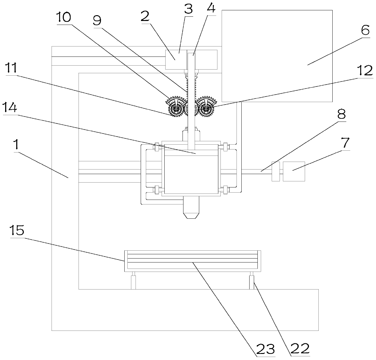
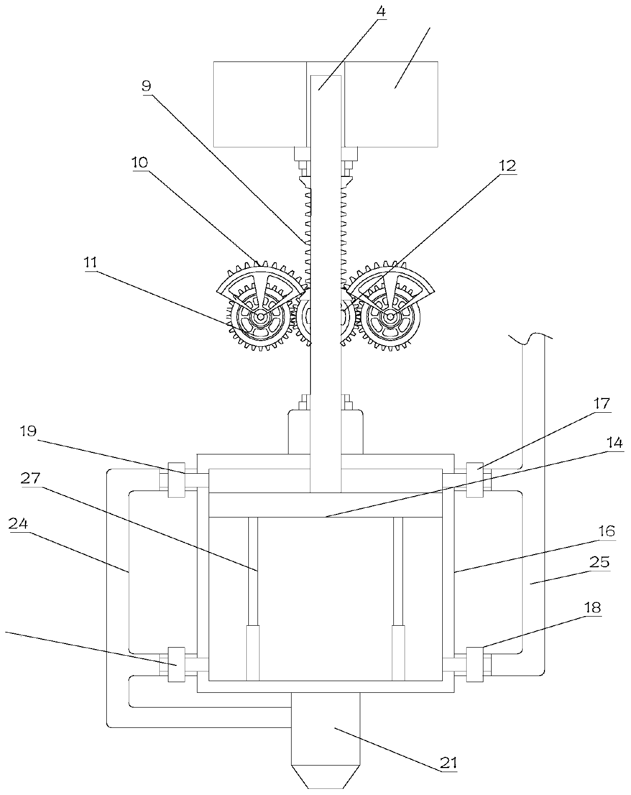
[0023] see Figure 1~3 , in Embodiment 1 of the present invention, a gluing device for continuous gluing for PCB boards, comprising a main body frame 1, a gluing mechanism 2 is arranged on the main frame 1, and a bearing is arranged below the gluing mechanism 2 Seat 15, the bottom of the bearing seat 15 is installed on the lifting cylinder 22, the lifting cylinder 22 is fixedly installed on the main frame 1, and the lifting cylinder 22 is set to adjust the height of the PCB board on the bearing seat 15, so that it can be glued The bottom of the mechanism 2 is close to the glue outlet 21, which is convenient for glue application; the glue outlet mechanism 2 includes a glue box 16 and a support block 3 slidably arranged on the main frame 1, and the glue box 16 and the support block 3 are fixedly connected , the inside of the plastic box 16 is provided with a piston 14 that slides up and down. The upper part of the piston 14 is provided with a C check valve 19 and an A check valv...

Embodiment 2

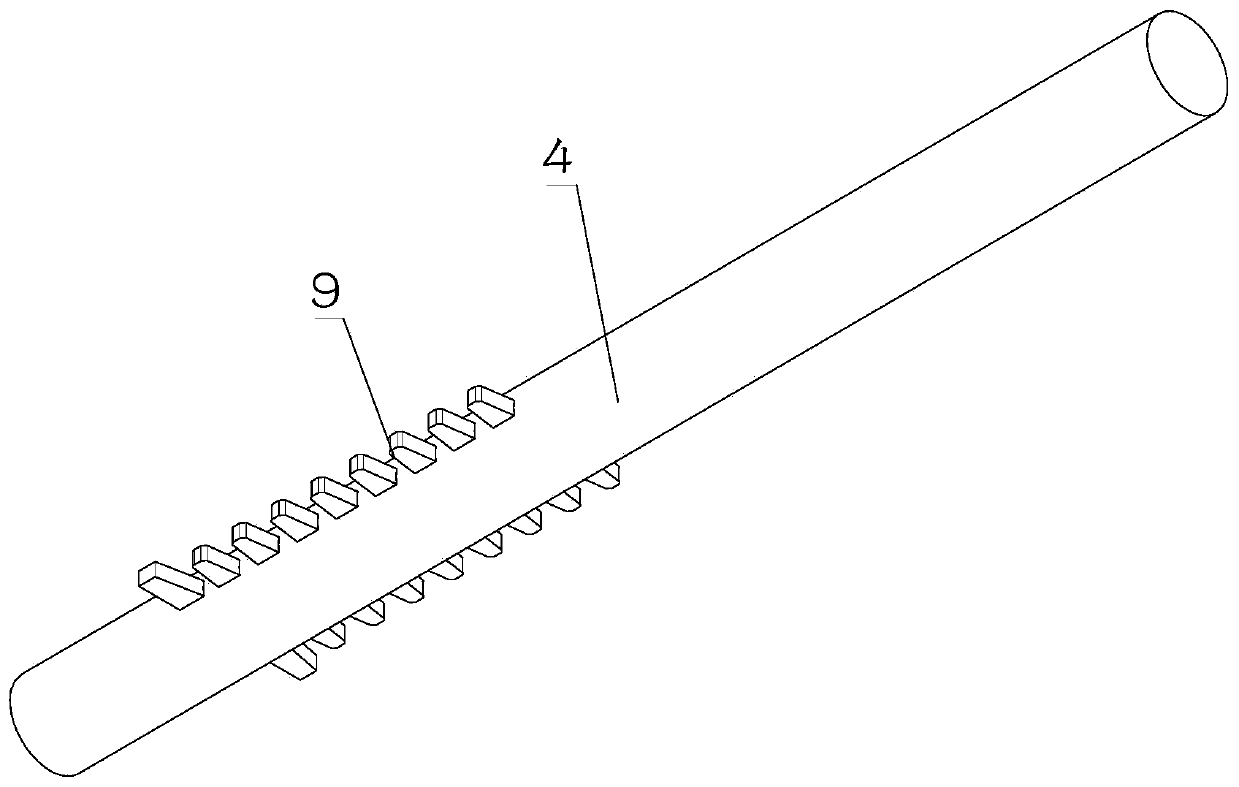
[0026] see Figure 1~3 The main difference between this embodiment 2 and embodiment 1 is that the reciprocating assembly includes a moving rod 4, the lower end of the moving rod 4 is fixedly mounted on the piston 14, and the upper end of the moving rod 4 is set in the through hole on the support block 3 Among them, the two sides of the moving rod 4 are respectively provided with racks 9, the racks 9 on both sides are respectively meshed with the incomplete gears 10 on both sides intermittently, and the incomplete gears 10 on both sides are coaxial with the driven gear 11 Set, the driven gear 11 on both sides meshes with the driving gear 12 respectively, the driving gear 12 provides power for the rotation of the driven gear 11, the driving gear 12 is installed on the output end of the B motor, and the B motor is fixedly installed on On the rubber box 16; the B motor drives the driving gear 12 to rotate, the driving gear 12 drives the driven gear 11 on both sides to rotate, and ...


PUM


Abstract

The invention discloses a gluing device for continuous glue feeding of a PCB, and relates to the technical field of PCB production. The device comprises a main body frame, a glue outlet mechanism is arranged on the main body frame, a bearing seat is arranged below the glue outlet mechanism, the bottom of the bearing seat is mounted on a lifting cylinder, the lifting cylinder is fixedly mounted onthe main body frame, the glue outlet mechanism comprises a glue box and a supporting block slidably arranged on the main body frame, a piston sliding up and down is arranged in the glue box, and a one-way valve C and a one-way valve A communicating with each other are arranged on the upper portion of the piston. A one-way valve D and a one-way valve B communicating with each other are arranged onthe lower portion of the piston. The output end of the one-way valve C and the output end of the one-way valve D communicate with a first pipeline, the output end of the first pipeline is connected tothe input end of a glue nozzle, and the glue nozzle is fixedly installed at the bottom of the glue box. The input end of the one-way valve A and the input end of the one-way valve B communicate witha second pipeline, and the input end of the second pipeline is externally connected with glue. The gluing device is stable in glue discharge and can achieve continuous glue discharge.

Description

technical field [0001] The invention relates to the technical field of PCB board production, in particular to a gluing device for continuous gluing for PCB boards. Background technique [0002] PCB, the Chinese name is printed circuit board, also known as printed circuit board, is an important electronic component, a support for electronic components, and a carrier for electrical connections of electronic components. Because it is made using electronic printing, it is called a "printed" circuit board. Silicone is a kind of one-component RTV silicone with good adhesion, high strength and no corrosion. Because of its excellent electrical insulation performance, sealing performance and aging resistance, it can be used for a long time in the range of -50°C to +250°C, so it is widely used in the process of bonding PCB boards. PCB boards have strict regulations on the bonding process. For example, the glue needs to be applied evenly, and the amount of glue used needs to be contr...

Claims


Application Information

Patent Timeline
Patent Type & Authority Applications(China)
IPC IPC(8): B05C5/02B05C13/02B05C11/10
CPCB05C5/0208B05C5/0225B05C11/1026B05C13/02
Inventor 王观波
Owner 南京奥亚美电子科技有限公司
Learn More