
Printed circuit board hole copper abnormity monitoring method

A printed circuit board and abnormal monitoring technology, which is applied in the direction of electronic circuit testing, electrical connection formation of printed components, electrical measurement, etc. Unable to use and other problems, to achieve the effect of testing the ability of the electroplating line, intuitive observation, and ingenious conception

Inactive Publication Date: 2020-04-28
惠州市大亚湾科翔科技电路板有限公司
View PDF5 Cites 2 Cited by
  • Summary
  • Abstract
  • Description
  • Claims
  • Application Information

AI Technical Summary

Problems solved by technology

[0002] In the printed circuit board, the hole copper is an important component that connects the lines of each layer. Its thickness and ductility are very important. When the client is used, when it is powered on for a long time or when there are extreme conditions of use, it is easy to have hole copper abnormalities, which will cause the electrical devices to be unusable.
[0003] At present, in order to solve the above problems, circuit board manufacturers often adopt the method of thickening the copper in the hole of the circuit board. This method of thickening the copper in the hole has the following deficiencies: 1. The processes adopted by different manufacturers are all different, but What they have in common is that the hole copper is thickened and electroplated once to increase the copper thickness of the hole copper and solve the problem of abnormal copper holes in the prior art. However, overall, this kind of hole copper thickening process is complicated and the holes Copper thickness uniformity is not high

Method used


Image

  • Printed circuit board hole copper abnormity monitoring method
  • Printed circuit board hole copper abnormity monitoring method

Examples


Embodiment Construction

[0032] The method for monitoring the copper via hole abnormality of the printed circuit board of the present invention will be described in further detail below with reference to specific embodiments and drawings.

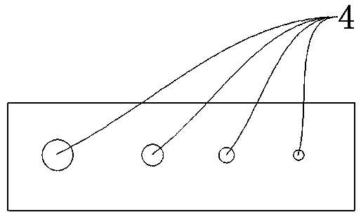
[0033] The present invention provides a method for monitoring copper hole abnormalities of printed circuit boards. The copper hole copper is monitored by the method for monitoring copper holes of printed circuit board. When the monitoring result shows abnormal conditions, the production can be stopped at the first time, and the cause of the defects can be checked immediately , To prevent bad circuit boards from leaving the plating process; and this monitoring method can also be used to detect blind holes, through holes 4 and the uniformity of copper plating.

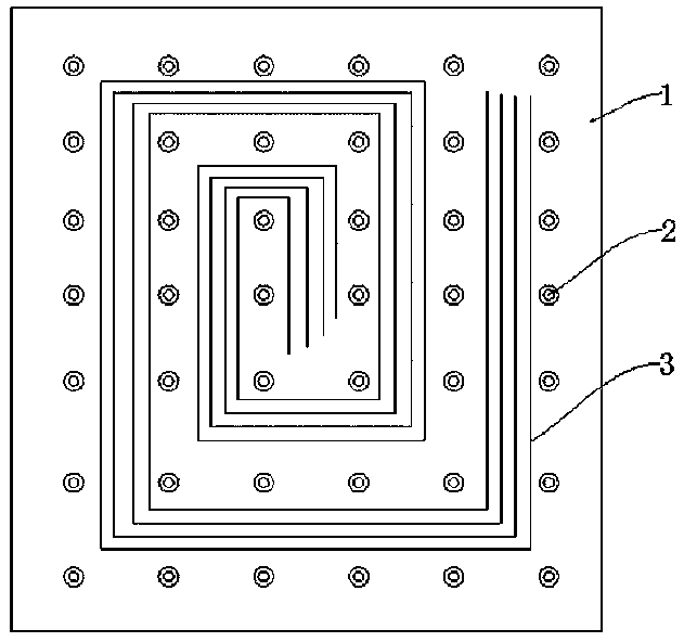
[0034] Reference figure 1 with figure 2 , A non-limiting embodiment of the present invention, a method for monitoring copper anomalies in a printed circuit board hole includes the following steps:

[0035] S1: Pro...


PUM


Abstract

The invention relates to a printed circuit board hole copper abnormity monitoring method, which comprises the following steps: S1, manufacturing a test board, including S1.1, selecting raw materials;S1.2, manufacturing copper testing PADs, namely, manufacturing a plurality of copper testing PADs on a circuit board as surface copper testing points, and enabling the plurality of surface copper testing points to be distributed in a square array shape; and S1.3, manufacturing through holes, namely, drilling a plurality of through holes with different sizes in the circuit board, and enabling the through holes with the same size to be arranged in the same row or the same column; and S2, carrying out a testing method, including S2.1, placing the test board and a normal board together, and conducting copper deposition, electroplating and board baking according to normal steps; S2.2, testing through hole resistance and surface copper data, namely, measuring the through hole resistance by usinga universal meter, and measuring the surface copper data by using the copper measuring PADs; and S2.3, performing screening and analysis, namely, screening out normal holes and abnormal holes according to test results in the step S3, observing the deep plating capacity in the normal holes by slicing the normal holes, and judging the cause of abnormality by slicing the abnormal holes and combiningsurface copper data. According to the invention, the problem of electroplating hole copper can be periodically and diversely monitored.

Description

Technical field [0001] The invention relates to the technical field of copper electroplating of printed circuit board holes, in particular to a method for monitoring abnormal copper of printed circuit board holes. Background technique [0002] In the printed circuit board, the thickness and ductility of the hole copper are very important as an important component to connect the various layers of the circuit. However, due to the production operation and material quality, the printed circuit board will have no holes and thin holes. Such phenomena, when used in the client, long-term power-on or extreme use conditions, the hole copper abnormality is likely to occur, which makes the electrical device unusable. [0003] At present, in order to solve the above problems, circuit board manufacturers often adopt the method of thickening the copper hole of the circuit board. This method of thickening the copper hole has the following shortcomings: 1. The process used by different manufacturer...

Claims


Application Information

Patent Timeline
IPC IPC(8): G01R31/28H05K3/42
CPCG01R31/2818H05K3/42
Inventor 周刚曾祥福王欣
Owner 惠州市大亚湾科翔科技电路板有限公司
Learn More