Rapid cooling device for joint of lining stainless steel pipe

A stainless steel pipe, rapid cooling technology, applied in the direction of auxiliary equipment, welding equipment, auxiliary welding equipment, etc., can solve the problems of easy water leakage, aging, and unsatisfactory cooling effect of plastic pipes

Inactive Publication Date: 2020-04-28
JIANGSU SHUNLONG PIPE TECH CO LTD
View PDF0 Cites 5 Cited by
  • Summary
  • Abstract
  • Description
  • Claims
  • Application Information

AI Technical Summary

Problems solved by technology

[0002] Lined stainless steel pipe is a composite thin-walled stainless steel pipe on the inner wall of the steel pipe. This bimetallic steel pipe greatly improves the corrosion resistance of the steel pipe in the process of water, hot water, gas, natural gas, and oil transportation. The surface is smooth and the fluid resistance Small, overcomes the defects of galvanized steel pipes that are easy to corrode, and plastic pipes that use hot-melt connections for water leakage and aging. It is an ideal product for upgrading gas, water, and oil steel pipes. After the welding is completed, the seam is in a high temperature state, and it must be cooled to proceed to the next step of processing. Most of the traditional cooling methods are artificially cooling. This cooling method is not only slow in efficiency, but also has an unsatisfactory cooling effect. The existing technology Introduction and defects, for this reason we propose a lined stainless steel pipe joint rapid cooling device to solve the above problems

Method used


Image

  • Rapid cooling device for joint of lining stainless steel pipe
  • Rapid cooling device for joint of lining stainless steel pipe

Examples


Embodiment Construction

[0018] The following will clearly and completely describe the technical solutions in the embodiments of the present invention with reference to the accompanying drawings in the embodiments of the present invention. Obviously, the described embodiments are only some, not all, embodiments of the present invention. Based on the embodiments of the present invention, all other embodiments obtained by persons of ordinary skill in the art without making creative efforts belong to the protection scope of the present invention.

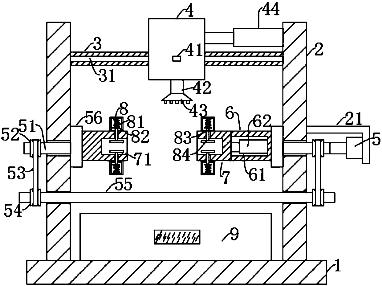
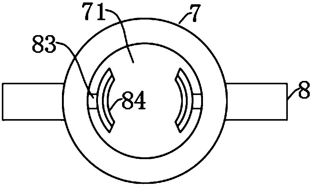
[0019] see Figure 1-2 , the present invention provides a technical solution: a quick cooling device for joints of lined stainless steel pipes, comprising a base 1, the top surface of both ends of the base 1 is symmetrically fixed with a vertical plate 2, and the upper ends of the opposite surface of the vertical plate 2 are symmetrically fixed Connected with a horizontal plate 3, the opposite surface of the horizontal plate 3 is slidingly clamped with a water...


PUM


Abstract

The invention discloses a rapid cooling device for a joint of a lining stainless steel pipe. The rapid cooling device comprises a base, wherein the two ends of the upper parts of the surfaces, opposite to each other, of bottom vertical plates are symmetrically and fixedly connected with a transverse plate; a water outlet pipe communicates with the middle position of the bottom of a water tank; a sprayer is fixedly connected to the bottom of the water outlet pipe; a motor is fixedly arranged on the side wall of a support; an output shaft of the motor is fixedly connected with one short shaft, and the other end of the short shaft penetrates through the side wall of one vertical plate; a driving wheel fixedly sleeves the outer wall of the short shaft and is connected with a driven wheel through a belt; the inner ring of the driven wheel fixedly sleeves a rotating shaft, and the other end of the rotating shaft penetrates through another vertical plate to be fixedly sleeved with the inner ring of a driven wheel which is far away from the motor; the side wall of the other end of a cylinder and the side wall of a turntable on the left side are rotatably attached with a clamping column andfixedly connected with a clamping column respectively; fixing grooves are respectively formed in the surfaces, opposite to each other, of the clamping columns; and the steel pipe is movably clamped in the fixing grooves. According to the rapid cooling device, the rotating shafts are utilized to rotate, so that the turntables at the two ends of the device are further driven to simultaneously rotate, finally the steel pipe are made to rotate along with the turntables, and the cooling range is wider.

Description

technical field [0001] The invention relates to the technical field of quick cooling of joints of stainless steel pipes, in particular to a quick cooling device for joints of lined stainless steel pipes. Background technique [0002] Lined stainless steel pipe is a composite thin-walled stainless steel pipe on the inner wall of the steel pipe. This bimetallic steel pipe greatly improves the corrosion resistance of the steel pipe in the process of water, hot water, gas, natural gas, and oil transportation. The surface is smooth and the fluid resistance Small, overcomes the defects of galvanized steel pipes that are easy to corrode, and plastic pipes that use hot-melt connections for water leakage and aging. It is an ideal product for upgrading gas, water, and oil steel pipes. After the welding is completed, the seam is in a high temperature state, and it must be cooled to proceed to the next step of processing. Most of the traditional cooling methods are artificially cooling....

Claims


Application Information

Patent Timeline
Patent Type & Authority Applications(China)
IPC IPC(8): B23K37/00B21C37/08
CPCB21C37/08B23K37/003
Inventor 蒋国型
Owner JIANGSU SHUNLONG PIPE TECH CO LTD
Why Eureka
Try Eureka