
Device for measuring pressure and friction of single condyle of knee joint

A measuring device and friction force technology, applied in joint implants, joint implants, medical science, etc., can solve the problem of inability to accurately judge and select the position and size of the meniscus liner, and the inability of the knee joint prosthesis to bear force Equilibrium and other issues to achieve the effect of increasing convenience, avoiding length restrictions, and being easy to use

Inactive Publication Date: 2020-04-28
牛依芃
View PDF15 Cites 1 Cited by
  • Summary
  • Abstract
  • Description
  • Claims
  • Application Information

AI Technical Summary

Problems solved by technology

[0006] In view of the above problems, the present invention provides a knee joint unicondylar pressure and friction measurement device to solve the problem that clinical doctors cannot accurately judge and select the placement position and size of the meniscal liner, which leads to implanted knee joint prosthetics. The technical problem that the body cannot be balanced by force

Method used


Image

  • Device for measuring pressure and friction of single condyle of knee joint
  • Device for measuring pressure and friction of single condyle of knee joint
  • Device for measuring pressure and friction of single condyle of knee joint

Examples


Embodiment Construction

[0043] The technical solution of the present invention will be further described in detail below in conjunction with the embodiments and the accompanying drawings.

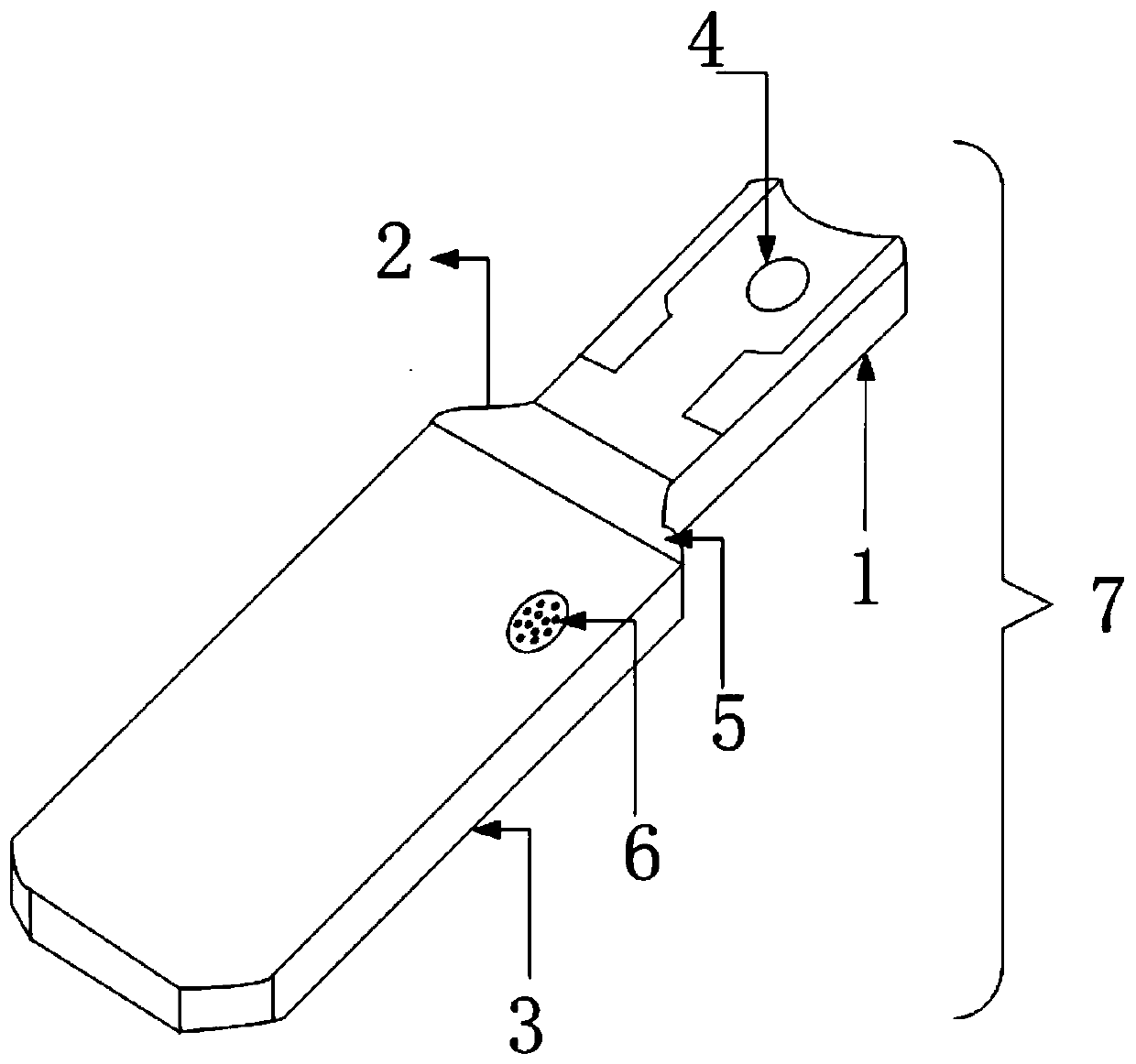
[0044] Such as figure 1 As shown, the knee joint unicondylar pressure and friction measuring device 7 according to an embodiment of the present invention includes a pressure measuring head 1, a connecting part 2 and a handle 3; connect.

[0045] The upper surface of the pressure measuring head 1 is provided with a half-moon-shaped groove, which matches the femoral unicondylar prosthesis (not shown), and the thickness of the central axis of the groove can be adjusted by replacing the measuring head, corresponding to different size, the adjustment range is 1-7mm. During the measurement process, the pressure measuring head can be replaced according to the specific size of the patient's femoral unicompartmental prosthesis and tibial prosthesis.

[0046] The pressure measuring head has a built-in pressure sensor 4, ...


PUM


Abstract

The invention provides a device for measuring interface pressure and pull-out friction between single condylar femoral prosthesis and tibial prosthesis during the process of single condyle replacementof the knee joint. The device for measuring the interface pressure and the pull-out friction between the single condylar femoral prosthesis and the tibial prosthesis during the process of the singlecondyle replacement of the knee joint is mainly composed of a pressure measurement head, a pull-out friction measurement connection part, and a hand-held handle; a pressure sensor is arranged on an upper surface of the pressure measurement head, and can be used for measuring the interface pressure between the single condylar femoral prosthesis and the tibial prosthesis; the pull-out friction measurement connection part is provided with a tension sensor which is used for indirectly measuring dynamic friction when the pressure measurement head is pulled out; a microprocessor module, a wireless transmission module and a power supply module are arranged inside the hand-held handle; and the microprocessor module converts received analog electrical signals into digital signals. During operationof the single condyle replacement of the knee joint, after installation of the single condylar femoral prosthesis and the tibial prosthesis, the device for measuring the interface pressure and the pull-out friction provided by the embodiment of the invention is used for measuring the pressure and the friction between the single condylar femoral prosthesis and the tibial prosthesis so as to facilitate understanding the pressure and the friction of the joint space during operation by a doctor, thereby improving accuracy of meniscus pad size and material selection so as to ensure that force on the implanted knee prosthesis is balanced.

Description

technical field [0001] The invention relates to a device for measuring pressure and friction force of a knee joint unicondyle. Background technique [0002] Osteoarthritis is a common degenerative disease, among which osteoarthritis in the knee joint has a high incidence. Advanced knee arthritis seriously affects the normal life of patients, and typical artificial knee replacement surgery is often used clinically for treatment. At present, common artificial knee replacements include: total knee replacement and unicompartmental knee replacement. [0003] Unicondylar replacement of the knee joint is an operation for the treatment of advanced knee joint diseases. It uses minimally invasive techniques, which can reduce the patient's pain and recover in a short period of time. The knee joint prosthesis includes two parts, metal and plastic, and the metal part includes the femoral, tibial and patella prostheses casted by titanium alloy or cobalt-chromium alloy. The plastic part...

Claims


Application Information

Patent Timeline
Patent Type & Authority Applications(China)
IPC IPC(8): A61F2/46
CPCA61F2/4657A61F2002/4666
Inventor 牛依芃曹家铭任鹏玲
Owner 牛依芃
Learn More