Seven-freedom-degree main operating handle for surgical robot
A surgical robot and a degree of freedom technology, applied in the field of medical devices, can solve the problems of inability to achieve gravity balance, easy fatigue of doctors, and burden of hand movement of doctors, and achieve the effect of enhancing anti-interference ability, simple structure, and reducing transmission errors.
- Summary
- Abstract
- Description
- Claims
- Application Information
AI Technical Summary
Problems solved by technology
Method used
Image
Examples
specific Embodiment approach 1
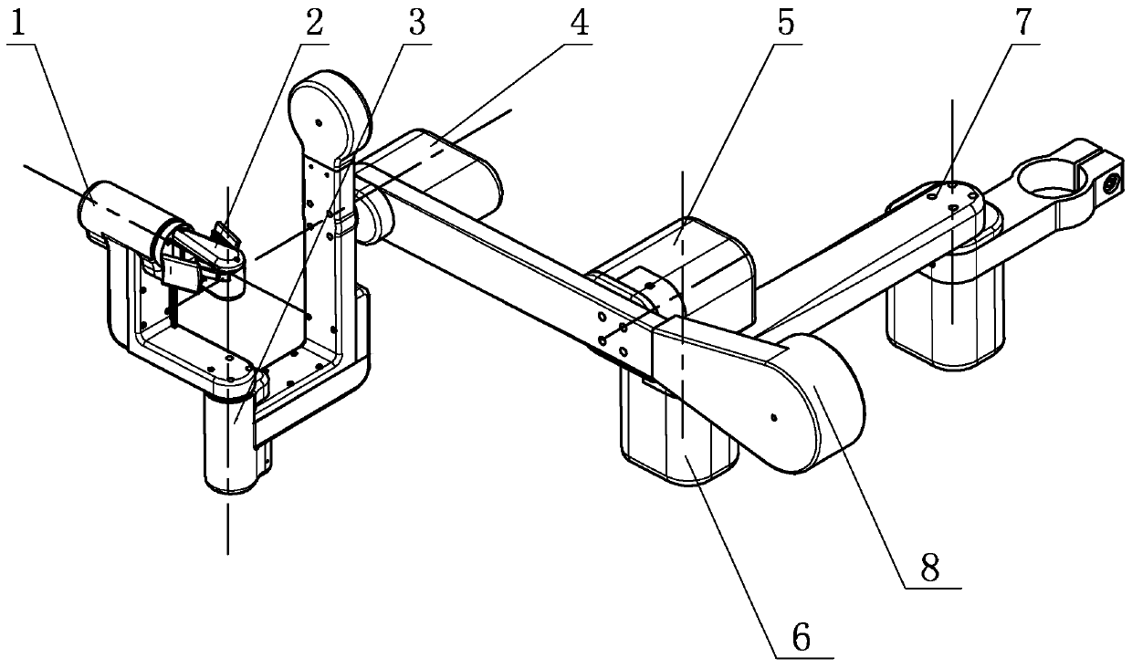
[0021] Specific implementation mode one: combine Figure 1 to Figure 12 Describe this embodiment, a seven-degree-of-freedom master manipulator for a surgical robot in this embodiment includes a waist joint 7, a shoulder joint 6, an elbow joint 5, a wrist pitch joint 4, and a wrist yaw joint 3, and the wrist yaw joint Joint 3, wrist pitch joint 4, elbow joint 5, shoulder joint 6 and waist joint 7 are connected sequentially, wherein wrist yaw joint 3, shoulder joint 6 and waist joint 7 rotate in the vertical direction, shoulder joint 6 and waist joint The joints 7 are connected by a connecting rod, the wrist pitch joint 4 and the elbow joint 5 rotate in the horizontal direction, the wrist yaw joint 3 and the wrist pitch joint 4 are connected by a connecting rod, the wrist pitch joint 4 and the elbow joint 5 are connected by a connecting rod, and it also includes a clamping mechanism 1, a wrist rolling joint 2 and a counterweight 8. The counterweight 8 is installed at the end of ...
specific Embodiment approach 2
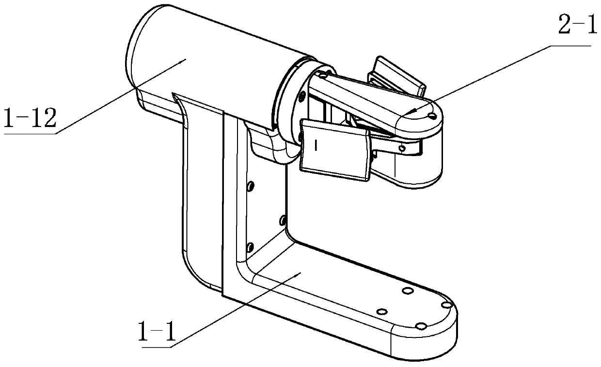
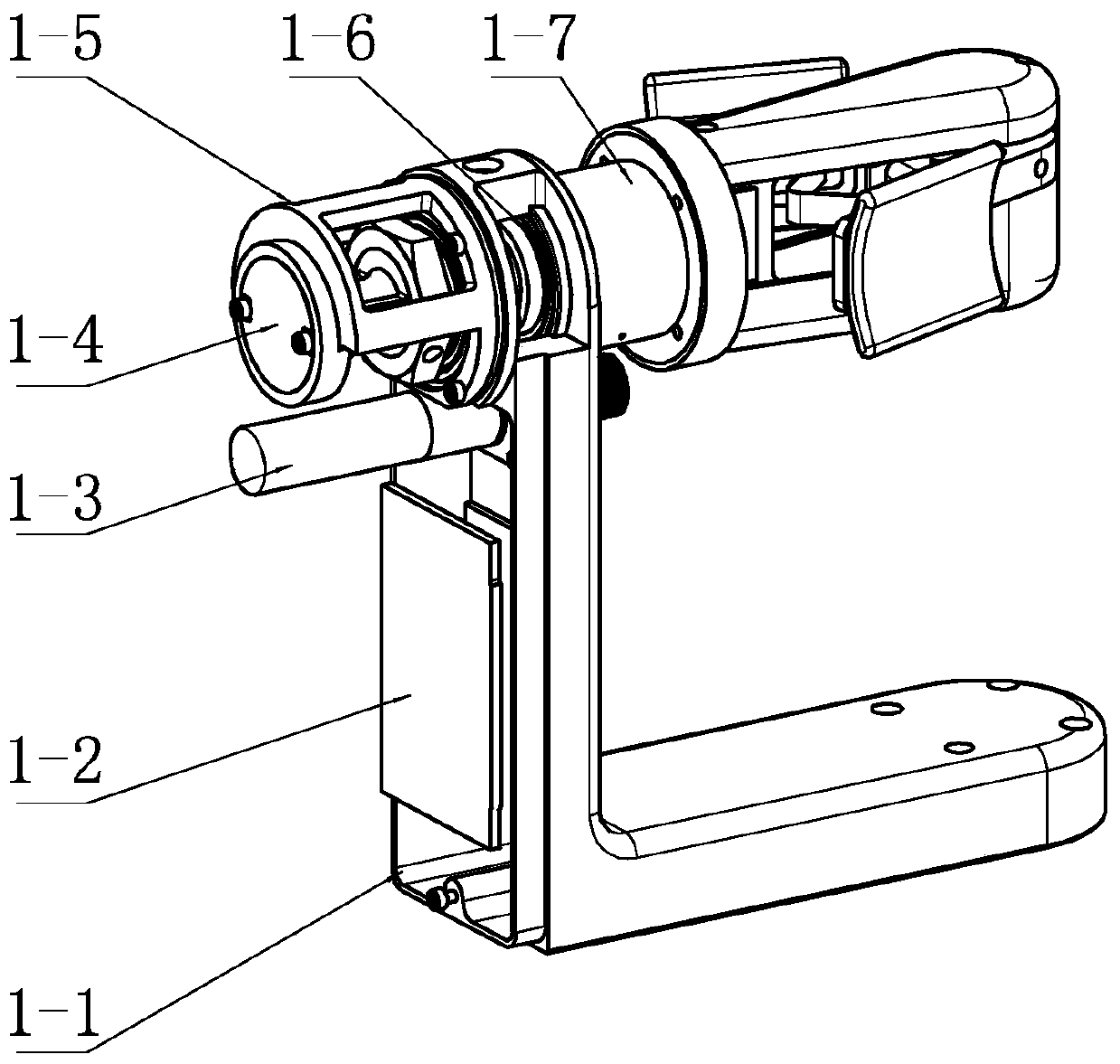
[0022] Specific implementation mode two: combination Figure 1 to Figure 5 Describe this embodiment, the clamping mechanism 1 of this embodiment comprises L-shaped connecting rod 1-1, driver 1-2, motor 1-3, encoder 1-4, encoder bracket 1-5, clamping bearing 1- 6. Rotary shaft 1-7, preload disc 1-8, preload screw 1-9, wire drum 1-10, steel wire 1-12, horizontal section of L-shaped connecting rod 1-1 and wrist yaw joint 3 Connection, the driver 1-2 is installed on the vertical section of the L-shaped connecting rod 1-1, and the motor 1-3 is horizontally installed on the vertical section of the L-shaped connecting rod 1-1 above the driver 1-2, and the motor 1-3 The output shaft is connected to the wire drum 1-10, the encoder bracket 1-5 is installed on the upper end of the vertical section of the L-shaped connecting rod 1-1, the encoder 1-4 is installed in the encoder bracket 1-5, and the rotating shaft 1 -7 is installed on the encoder bracket 1-5 at the upper end of the vertica...
specific Embodiment approach 3
[0024] Specific implementation mode three: combination Figure 8 The present embodiment will be described. The steel wire 1-12 of the present embodiment is wound around the wire drum 1-10 and the rotating shaft 1-7 in a figure-of-eight pattern. With such arrangement, the pre-tightening of the steel wire is firm and reliable. Other compositions and connections are the same as those in Embodiment 1 or Embodiment 2.
[0025] The motor 1-3 of this embodiment is consolidated with the L-shaped connecting rod 1-1, and is placed parallel to the axis of the rotating shaft 1-7. The shaft is fixed. The wire drum 1-10 and the rotating shaft 1-7 are connected and driven by steel wire ropes at both ends, and the way of winding the steel wire is 8-shaped winding. More specifically, one of the ends of the two sections of steel wire is fixed on two positions ① and ② of the wire drum in Fig. The steel wire rope of ③ or ④ needs to be knotted inside the rotating shaft 1-7, and the steel wire ...
PUM
 Abstract
Description
Claims
Application Information
 - R&D
- Intellectual Property
- Life Sciences
- Materials
- Tech Scout
- Unparalleled Data Quality
- Higher Quality Content
- 60% Fewer Hallucinations
Browse by: Latest US Patents, China's latest patents, Technical Efficacy Thesaurus, Application Domain, Technology Topic, Popular Technical Reports.
© 2025 PatSnap. All rights reserved.Legal|Privacy policy|Modern Slavery Act Transparency Statement|Sitemap|About US| Contact US: help@patsnap.com


