Fundus imaging device and imaging method
An imaging method and imaging device technology, which are applied in the fields of ophthalmoscope, eye testing equipment, medical science, etc., can solve the problems of difficult prior information of optical systems, lack of universal applicability, and difficult operation, etc. Distinguishing detection imaging, less susceptible to interference, and the effect of improving resolution
- Summary
- Abstract
- Description
- Claims
- Application Information
AI Technical Summary
Problems solved by technology
Method used
Image

Examples
Embodiment 1
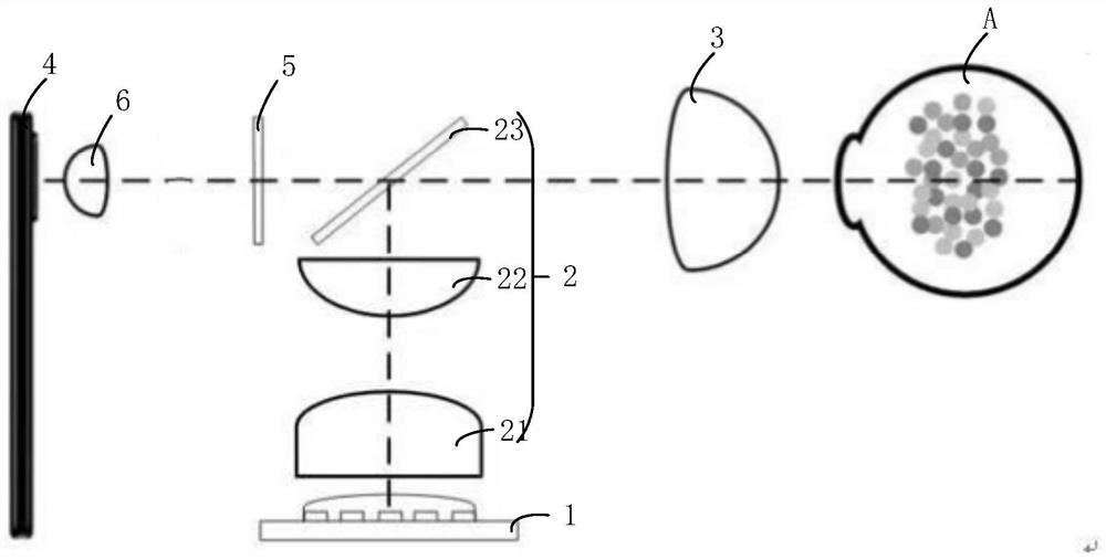
[0045] See figure 1 , figure 1 It is a schematic structural diagram of a fundus imaging device provided by an embodiment of the present invention. The imaging device is mainly used for fundus imaging, including fundus imaging with turbidity in the eyeball and fundus imaging without turbidity in the eyeball, and can also be applied to imaging of thin biological tissues, including thin biological tissues with hidden objects such as physiological lesions. Tissues and thin biological tissues without hidden objects such as physiological lesions. This embodiment is mainly described by taking fundus imaging in which there is opacity in the eyeball (the lens or vitreous body inside the eyeball is opaque) as an example.
[0046] figure 1 The fundus imaging device includes: LED light source 1 , light modulation unit 2 , detection unit 3 , light filtering unit 5 , relay lens 6 and optical signal receiver 4 . Among them, A is the target eyeball with turbidity.
[0047] The LED light ...
Embodiment 2
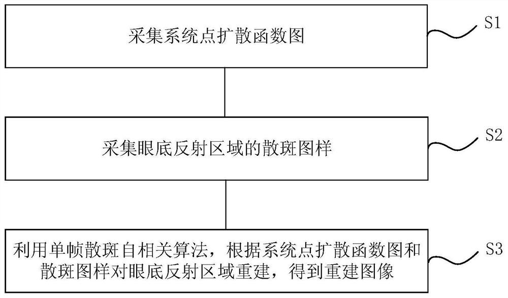
[0060] On the basis of Example 1, please refer to figure 2 , figure 2 It is a schematic flowchart of a fundus imaging method provided by an embodiment of the present invention. The fundus imaging method utilizes the fundus imaging device of Embodiment 1 to image the turbid fundus, specifically including steps:
[0061] S1. The point spread function graph of the acquisition system.
[0062] Specifically, firstly, the target eyeball A is replaced by a reflective pinhole, which is placed on the back focal plane of the detection unit 3 . Then, turn on the LED light source 1 to make it emit spatially incoherent light. Next, make the spatially incoherent light pass through the light modulation unit 2, modulate the spatially incoherent light into parallel light rays, and change the optical path direction of the parallel light rays. After that, the detection unit 3 is used to converge the parallel light rays after changing the direction of the optical path to obtain the incident...
Embodiment 3
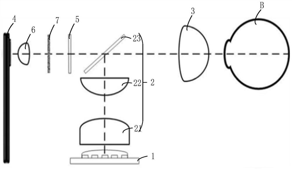
[0081] See image 3 , image 3 It is a schematic structural diagram of another fundus imaging device provided by an embodiment of the present invention. The fundus imaging device mainly images the fundus without turbidity in the eyeball, and can realize super-resolution imaging of the fundus; the fundus imaging device can also be applied to super-resolution imaging of thin biological tissues with physiological lesions. In this embodiment, the fundus super-resolution imaging is taken as an example for specific description.
[0082] image 3 The fundus imaging device includes: LED light source 1 , light modulation unit 2 , detection unit 3 , light filter unit 5 , relay lens 6 , scattering medium 7 and optical signal receiver 4 . image 3 Among them, B is the eyeball without turbidity.
[0083] For the description of the LED light source 1 , the light modulation unit 2 , the detection unit 3 , the light filter unit 5 , the relay lens 6 and the optical signal receiver 4 , plea...
PUM
 Abstract
Description
Claims
Application Information
 - R&D
- Intellectual Property
- Life Sciences
- Materials
- Tech Scout
- Unparalleled Data Quality
- Higher Quality Content
- 60% Fewer Hallucinations
Browse by: Latest US Patents, China's latest patents, Technical Efficacy Thesaurus, Application Domain, Technology Topic, Popular Technical Reports.
© 2025 PatSnap. All rights reserved.Legal|Privacy policy|Modern Slavery Act Transparency Statement|Sitemap|About US| Contact US: help@patsnap.com