High-power inductor
A high-power, inductive technology, applied in transformer/inductor housing, transformer/inductor cooling, transformer/inductor coil/winding/connection, etc., can solve the problem of low current resistance, power consumption, magnetic material air gap increase. Large and other problems, to achieve the effect of high current load capacity, lower operating temperature, and stable air gap structure
- Summary
- Abstract
- Description
- Claims
- Application Information
AI Technical Summary
Problems solved by technology
Method used
Image
Examples
Embodiment 1
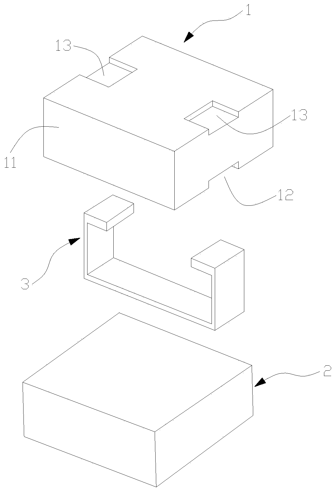
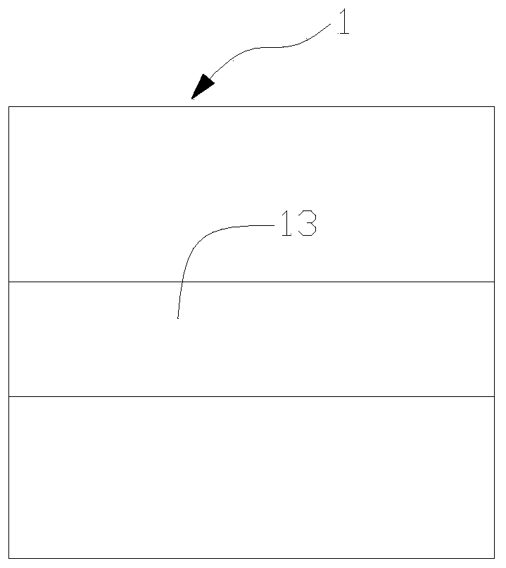
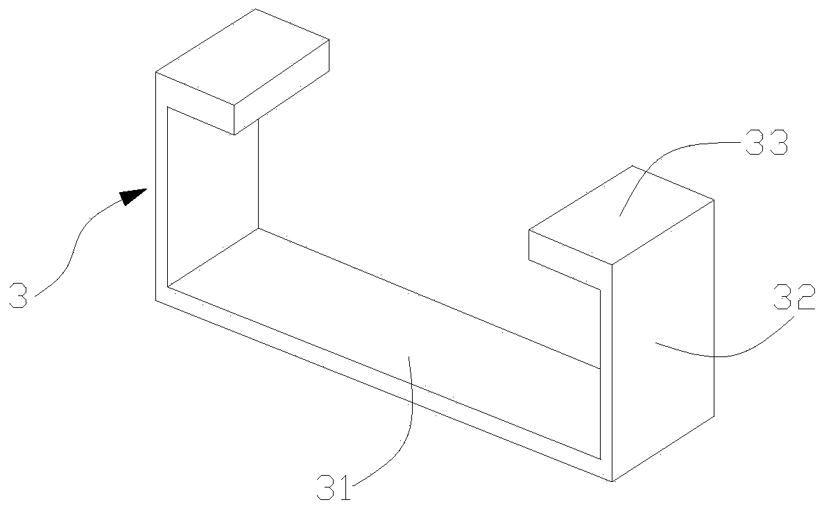
[0033] Such as Figure 1 to Figure 4 As shown, Embodiment 1 of the present invention proposes a high-power inductor, which includes a first magnetic base 1, a second magnetic base 2, and a "U"-shaped connecting terminal 3, and the first magnetic base 1 is provided with A slot structure for fixing the connection terminal 3. The connecting terminal 3 functions as an induction coil, and its end forms a soldering pin electrically connected to the circuit on the main board of the electronic instrument. The opposite connecting end faces of the second magnetic base 2 and the first magnetic base 1 are connected and fixed by adhesive glue, and an air gap 4 is formed between the opposite connecting end faces, that is, the relative connection between the second magnetic base 2 and the first magnetic base 1 The separation gap between the end faces.
[0034] Further, in the first embodiment, the connecting terminal 3 includes a connecting arm 31 straddling the first magnetic base 1 and b...
Embodiment 2
[0038] Such as Figure 3 to Figure 6 As shown, Embodiment 2 of the present invention proposes a high-power inductor. The high-power inductor includes a first magnetic base 1, a second magnetic base 2, and a "U"-shaped connecting terminal 3. The first magnetic base 1 is provided with A slot structure for fixing the connection terminal 3. The connecting terminal 3 functions as an induction coil, and its end forms a soldering pin electrically connected to the circuit on the main board of the electronic instrument. The opposite connecting end faces of the second magnetic base 2 and the first magnetic base 1 are connected and fixed by adhesive glue, and an air gap 4 is formed between the opposite connecting end faces, that is, the relative connection between the second magnetic base 2 and the first magnetic base 1 The separation gap between the end faces.
[0039] Further, in the second embodiment, the connecting terminal 3 includes a connecting arm 31 straddling the first magnet...
Embodiment 3
[0043] Such as Figure 7 As shown, on the basis of Embodiment 1 and Embodiment 2 of the present invention, the adhesive glue used to bond and fix the opposite connection end surfaces of the second magnetic base 2 and the first magnetic base 1 is on the connection surface of the two One layer of adhesive glue layer 6 is formed at the place. The adhesive layer 6 is mixed with a number of glass bead particles 7 with the same diameter. The diameter of the glass bead particles 7 is adjusted according to the inductance. Glass bead particles 7 with different diameters can make the size of the formed air gap 4 vary. The same, thus determining the size of the inductance. The size of the air gap 4 , that is, the distance between the opposite connecting end surfaces of the second magnetic base 2 and the first magnetic base 1 , is adapted to the diameter of the glass bead particles 7 . Such as Figure 8 As shown, it is a schematic diagram of the cross-sectional structure of the bonding...
PUM
 Abstract
Description
Claims
Application Information
 - R&D
- Intellectual Property
- Life Sciences
- Materials
- Tech Scout
- Unparalleled Data Quality
- Higher Quality Content
- 60% Fewer Hallucinations
Browse by: Latest US Patents, China's latest patents, Technical Efficacy Thesaurus, Application Domain, Technology Topic, Popular Technical Reports.
© 2025 PatSnap. All rights reserved.Legal|Privacy policy|Modern Slavery Act Transparency Statement|Sitemap|About US| Contact US: help@patsnap.com


