A low-field quantum resistance measuring instrument

A resistance measuring instrument, quantum technology, applied in the direction of measuring resistance/reactance/impedance, measuring devices, measuring electrical variables, etc., can solve the problem of inability to realize the industrialization and wide application of quantum resistance measuring instruments, immature development of vascular machines, The structure of the vascular machine is complex and other problems, so as to promote the promotion and application, occupy a small area, and improve the accuracy of delivery

Active Publication Date: 2022-05-24
BEIJING DONGFANG MEASUREMENT & TEST INST
View PDF9 Cites 0 Cited by
  • Summary
  • Abstract
  • Description
  • Claims
  • Application Information

AI Technical Summary

Problems solved by technology

However, the structure of the vascular machine is complicated, the price is expensive, and the service life is limited, and the development of the domestic vascular machine is not yet mature, so the industrialization and wide application of the quantum resistance measuring instrument in China cannot be realized.

Method used


Image

  • A low-field quantum resistance measuring instrument

Examples


Embodiment 1

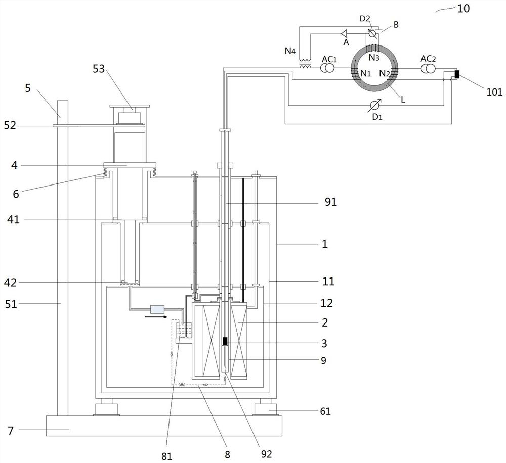
[0028] A low-field quantum resistance measuring instrument, such as figure 1 As shown, including Dewar cold tank 1, superconducting magnet 2, graphene quantum Hall resistance chip 3, current comparator bridge 10 and multistage GM refrigerator 4, described graphene quantum Hall resistance chip 3 is located in Inside the magnetic field generated by the superconducting magnet 2, the multi-stage GM refrigerator 4 provides a cold source for the superconducting magnet 2 and the quantum Hall resistance chip 3; the shell of the Dewar cold tank 1 is provided with a cold head insert. The hole is used to insert the cold head of the multistage GM refrigerator 4 into the Dewar cold tank 1, to the superconducting magnet 2, the graphene quantum Hall resistance located in the Dewar cold tank 1 The chip 3 provides a cold source; it also includes a suspension mechanism 5 provided independently of the Dewar cold tank, the suspension mechanism 5 is used to suspend and fix the multi-stage GM refri...

Embodiment 2

[0037]The difference between this embodiment and the above-mentioned embodiment is that the sample rod 91 is a Dewar sample rod, and the graphene quantum Hall resistance chip 3 is placed inside the Dewar sample rod. Preferably, the graphene quantum Hall resistance chip 3 can be replaced with a low-field gallium arsenide quantum Hall resistance chip, and the low-field gallium arsenide quantum Hall resistance chip refers to a low-field gallium arsenide quantum Hall resistance chip that can GaAs quantum Hall resistance chip that normally completes the measurement in the magnetic field. The Dewar sample rod 91 is provided with a chip conversion device which can be connected with both the graphene quantum Hall resistance chip and the low-field gallium arsenide quantum Hall resistance chip. The low-field quantum resistance measuring instrument of the present invention further includes a JT (Joule-Thomson) cycle system 8 capable of reducing the temperature of the position where the q...


PUM


Abstract

A low-field quantum resistance measuring instrument, using a GM refrigerator with mature technology and low maintenance cost as a cold source for quantum Hall resistance measurement, and setting the multi-stage GM refrigerator and Dewar cold tank independently of each other through a suspension mechanism to reduce The impact of vibration on the measurement uncertainty of the quantum Hall resistance chip, using the low-frequency current comparator bridge at room temperature to transfer the value of the quantum Hall resistance to the measured resistance, and keep the measurement uncertainty of the quantum resistance measuring instrument at 10 ‑8 The order of magnitude makes it possible for the quantum resistance measuring instrument to operate continuously, saving a lot of money in terms of equipment cost and operating cost, and does not need to consume additional scarce resource liquid helium, avoiding the waste of resources. The JT circulation system is used to make the quantum resistance measuring instrument use the graphene quantum Hall resistance chip and the low-field gallium arsenide quantum Hall resistance chip for measurement, and a detachable sample rod is designed, and a chip conversion device is set in the sample rod , improving the versatility of the device.

Description

technical field [0001] The invention relates to a quantum resistance measuring technology, in particular to a low-field quantum resistance measuring instrument. Background technique [0002] 100 years after the discovery of the Hall effect, German scientists von Kritzing, Dorda, and Piper discovered that high-mobility semiconductor devices—such as heterojunction devices of silicon or gallium arsenide—are cooled to several K When the temperature is applied with a magnetic field of about 10T, when the current through the device is fixed, there are some areas on the curve of Hall voltage versus magnetic induction intensity. In these areas, when the magnetic induction intensity changes, the Hall voltage remains unchanged, This phenomenon is called the quantized Hall effect. At this time, the electron is completely polarized, and the energy of the spin is constant and can be ignored. It is a phenomenon that occurs when the two-dimensional electron gas (2DEG) is fully quantized u...

Claims


Application Information

Patent Timeline
Patent Type & Authority Patents(China)
IPC IPC(8): G01R27/08
CPCG01R27/08
Inventor 黄晓钉宋海龙徐思伟于珉蔡建臻门伯龙孙毅潘攀
Owner BEIJING DONGFANG MEASUREMENT & TEST INST
Why Eureka
Try Eureka