Eureka AIR delivers breakthrough ideas for toughest innovation challenges, trusted by R&D personnel around the world.

Anti-pollution and anti-blocking asphalt conveying pipe

A technology for conveying pipes and asphalt, which is applied in the direction of pipes, rigid pipes, and pipeline protection. It can solve the problems of asphalt agglomeration, blockage of pipes, and obstruction of asphalt transmission, and achieve the effects of improving fluidity, avoiding blockage, and efficient heating effect

Active Publication Date: 2020-04-24
广东诚泰投资集团有限公司
View PDF7 Cites 0 Cited by
  • Summary
  • Abstract
  • Description
  • Claims
  • Application Information

AI Technical Summary

Problems solved by technology

In the prior art, in order to ensure that the asphalt can be transported in the pipeline, a heating structure is provided outside the pipeline, and the pipeline is heated by the heating structure to make the asphalt show a certain fluidity, but this heating structure can only treat the asphalt near the pipeline wall. For heating, the asphalt in the center of the pipe needs to be transferred through the edge asphalt to obtain heat energy. The asphalt around the center of the pipe is prone to agglomeration, and the agglomeration will block the pipe. Even if there is no agglomeration, the asphalt with insufficient fluidity will adhere to the inner wall of the pipe And the formation of fouling, hindering the transmission of subsequent asphalt

Method used


Image

  • Anti-pollution and anti-blocking asphalt conveying pipe
  • Anti-pollution and anti-blocking asphalt conveying pipe
  • Anti-pollution and anti-blocking asphalt conveying pipe

Examples


Embodiment Construction

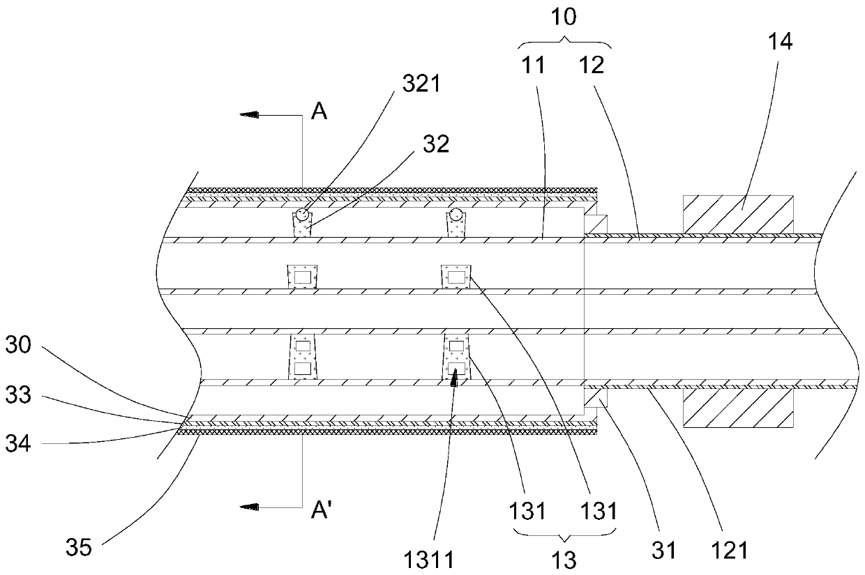
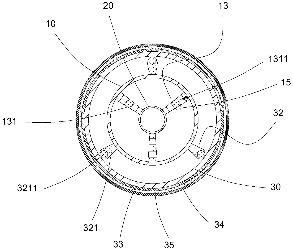
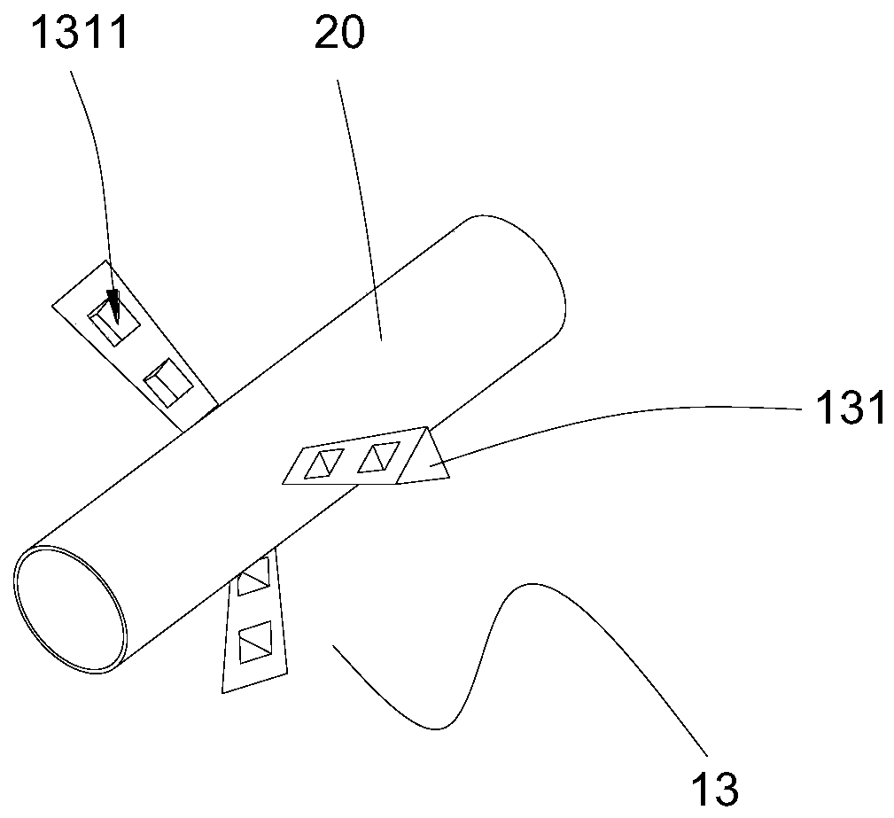
[0021] In order to further understand the features, technical means, and specific objectives and functions achieved by the present invention, the present invention will be further described in detail below in conjunction with the accompanying drawings and specific embodiments.

[0022] refer to Figure 1 to Figure 3 .

[0023] The embodiment of the present invention discloses an anti-fouling and anti-blocking asphalt delivery pipe, which includes a delivery pipe body 10, and an inner heat-conducting oil pipe 20 is arranged inside the delivery pipe body 10, and the space between the delivery pipe body 10 and the inner heat-conducting oil pipe 20 is formed In the material delivery chamber for circulating asphalt, the inner heat transfer oil pipe 20 forms an inner heat transfer oil chamber for circulating heat transfer oil. The delivery pipe body 10 includes a first material pipe 11 and a second material pipe 12 connected to each other. The first material pipe 11 It is integrall...


PUM


Abstract

The invention provides an anti-pollution and anti-blocking asphalt conveying pipe. The anti-pollution and anti-blocking asphalt conveying pipe comprises a conveying pipe body; an inner heat conductionoil pipe is arranged in the conveying pipe body; the conveying pipe body comprises a first material pipe and a second material pipe which are communicated with each other; the first material pipe issleeved with an outer heat conduction oil pipe; a plurality of first positioning supports which are distributed at equal intervals are connected between the material conveying pipe body and the innerheat conduction oil pipe; each first positioning support comprises at least three first positioning columns; the first positioning columns are triangular prisms; a hollow shaft motor is connected to the exterior of the second material pipe; a temperature sensor is arranged in the material conveying pipe body; a plurality of second positioning supports distributed at equal intervals are connected between the first material pipe and the outer heat conduction oil pipe; each second positioning support comprises at least three second positioning columns; and one end of each second positioning column is connected with the outer heat conduction oil pipe through a ball. With the anti-pollution and anti-blocking asphalt conveying pipe of the invention adopted, asphalt can be uniformly heated; the conveying pipe body is adopted; the conveying pipe body can turn over, so that the fluidity of the asphalt can be improved, and therefore, the asphalt can be smoothly conveyed in the conveying pipe.

Description

technical field [0001] The invention relates to an asphalt material pipe, and in particular discloses an anti-fouling and anti-blocking asphalt conveying pipe. Background technique [0002] The conveying pipe is used to transport liquid or fluid solid-liquid mixed materials. Asphalt is solid at room temperature, and becomes fluid solid-liquid mixed state after heating. Asphalt is a dark brown complex mixture composed of hydrocarbons of different molecular weights and their non-metallic derivatives. It is a kind of high-viscosity organic liquid and is mainly used in coatings, plastics, rubber and other industries and paving roads. [0003] The asphalt needs to reach a certain temperature in the pipeline, otherwise the solid asphalt cannot be transported in the pipeline. In the prior art, in order to ensure that the asphalt can be transported in the pipeline, a heating structure is provided outside the pipeline, and the pipeline is heated by the heating structure to make the ...

Claims


Application Information

Patent Timeline
Patent Type & Authority Applications(China)
IPC IPC(8): F16L9/14F16L53/32F16L57/02F16L59/02F17D1/18
CPCF16L9/14F16L57/02F16L59/028F16L59/029F17D1/18F16L53/32
Inventor 翁力
Owner 广东诚泰投资集团有限公司
Why Eureka
Eureka Blog
Learn More