Inertia force balance type two-dimensional piston air compressor

A balanced and inertial force technology, applied in the direction of piston pumps, liquid displacement machinery, mechanical equipment, etc., can solve the problems of complex multi-stage compression structure, low exhaust pressure, difficult sealing, etc., and achieve light weight, reduced Effects of vibration, friction reduction, and frictional heating

Pending Publication Date: 2020-04-24
ZHEJIANG UNIV OF TECH
View PDF0 Cites 2 Cited by
  • Summary
  • Abstract
  • Description
  • Claims
  • Application Information

AI Technical Summary

Problems solved by technology

Reciprocating piston compressors use single or multiple plungers, grooves on the plungers and sealing rings, and form compression chambers with the cylinder for suction and exhaust; this type of compressor has strong adaptability and is easy to obtain high-pressure gas, but Limited by the reciprocating inertial force, the speed is not high, the vibration is large, the multi-stage compression structure is complex, and there are many wearing parts
The rotary air compressor has one or more rotors rotating in the cylinder, which causes periodic changes in the working volume in the cylinder to perform suction and exhaust; this type of compressor has a simple structure, stable exhaust, and small vibration, but every rotation Inhale and exhaust once a week, the exhaust pressure is low, the sealing is difficult, and the efficiency is low

Method used


Image

  • Inertia force balance type two-dimensional piston air compressor
  • Inertia force balance type two-dimensional piston air compressor
  • Inertia force balance type two-dimensional piston air compressor

Examples


Embodiment Construction

[0046] The technical solution of the present invention will be further described below in conjunction with the accompanying drawings.

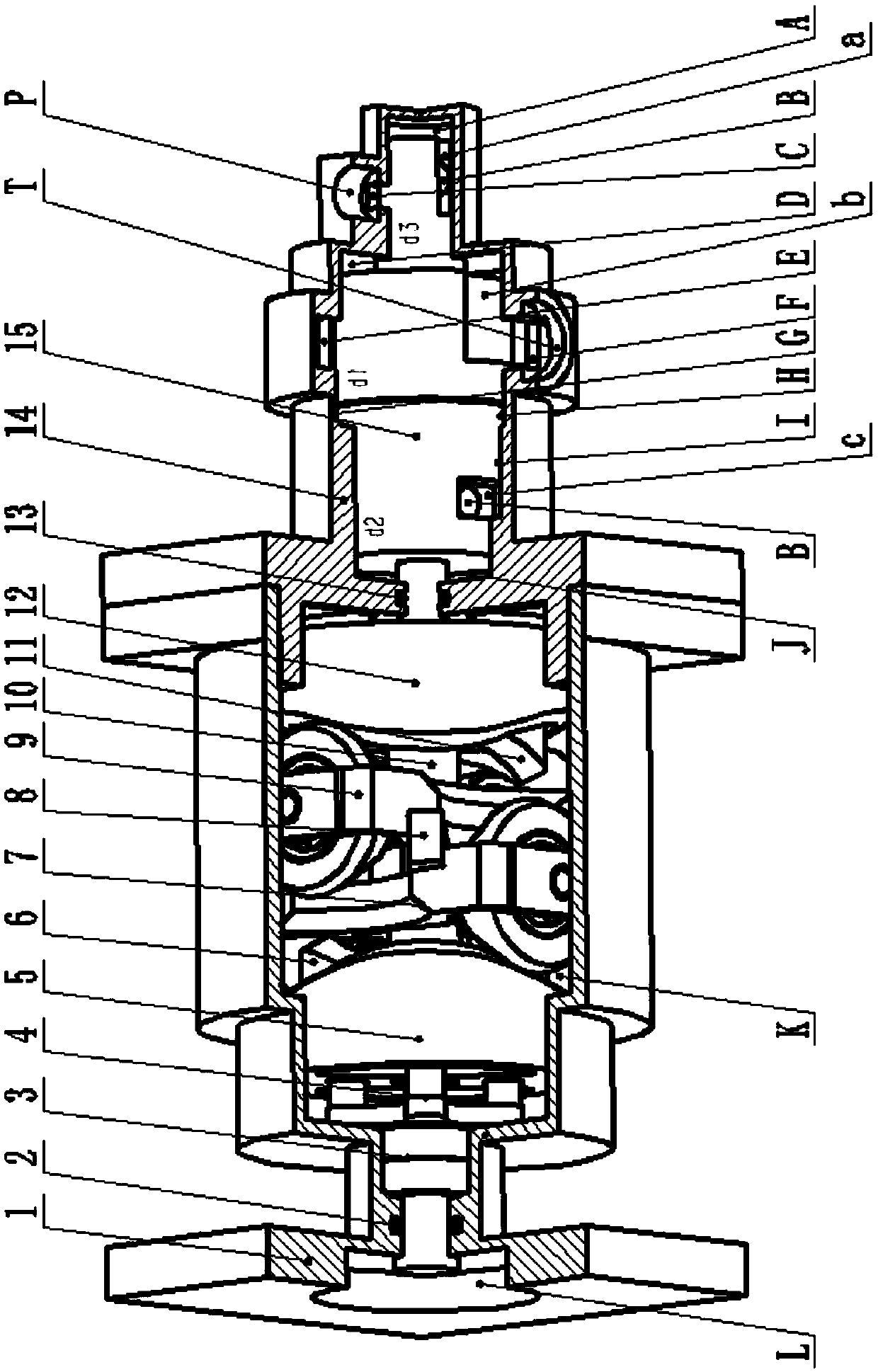
[0047] Such as figure 1 As shown, the inertia force balanced two-dimensional piston air compressor consists of a connecting plate 1, a transmission shaft 4, a left balance guide rail 5, a left guide rail 6, a left roller assembly 7, a cross support rod 8, a right roller assembly 9, Piston bushing 10, right guide rail 11, right balance guide rail 12, cylinder body 14, piston 15 etc. constitute. The connecting plate 1 and the cylinder body 14 are fixedly connected by threads, the left guide rail 6 and the right guide rail 11 are symmetrically and fixedly installed on the left shaft of the piston 15, and the left balance guide rail 5 and the right balance guide rail 12 are symmetrically and fixedly installed on the piston bushing 10. The constant acceleration and deceleration curved surfaces are staggered by 90 degrees in the circumferential dir...


PUM


Abstract

An inertia force balance type two-dimensional piston air compressor is composed of a connecting plate, a transmission shaft, a guide rail, a balance guide rail, a piston shaft sleeve, a cross-shaped supporting rod, roller assemblies, a piston, a cylinder body and the like. The connecting plate is fixedly connected with the cylinder body through threads; the guide rail is fixedly arranged on a piston left side shaft, the balance guide rail is fixedly arranged on the piston shaft sleeve, the piston shaft sleeve can be sleeved on the piston left side shaft in an axial sliding mode, the cross-shaped supporting rod is fixedly arranged on the cylinder body, and the two groups of roller assemblies are fixed on the cross-shaped supporting rod through constraint of the guide rail and arranged in a90-degree staggered mode in the circumferential direction; one end of the guide rail and one end of the balance guide rail are equal-acceleration and equal-deceleration curved surfaces in the same shape and staggered by 90 degrees in the circumferential direction. The mass sum of a balance rotor composed of the balance guide rail and the piston shaft sleeve is equal to the mass sum of a rotor composed of the guide rail and the piston, and when the guide rail drives the rotor to perform equal acceleration and equal deceleration motion, the balance guide rail performs homodromous equal acceleration and equal deceleration staggered motion in the circumferential direction and reversed equal acceleration and equal deceleration staggered motion in the axial direction to counteract inertia forcegenerated by axial motion of the rotor.

Description

technical field [0001] The invention relates to the technical field of gas compression equipment, in particular to an inertial force balanced two-dimensional piston air compressor. Background technique [0002] An air compressor is a mechanical device that compresses the volume of gas, increases the pressure of the gas, and transports the gas. It can reduce the volume of the gas, increase the pressure, and has a certain kinetic energy. It can be used as a mechanical power. Its application range and industry are very wide. [0003] Commonly used air compressors include reciprocating piston compressors and rotary compressors. Reciprocating piston compressors use single or multiple plungers, grooves on the plungers and sealing rings, and form compression chambers with the cylinder for suction and exhaust; this type of compressor has strong adaptability and is easy to obtain high-pressure gas, but Limited by the reciprocating inertial force, the speed is not high, the vibration...

Claims


Application Information

Patent Timeline
Patent Type & Authority Applications(China)
IPC IPC(8): F04B25/02F04B37/12F04B35/01F04B39/00F04B39/12
CPCF04B25/02F04B35/01F04B37/12F04B39/0005F04B39/122
Inventor 阮健宋占凯邢彤赵建涛孟彬赵伟
Owner ZHEJIANG UNIV OF TECH
Why Eureka
Try Eureka