
Shield machine cutter head and shield machine

A shield machine and cutter head technology, which is applied in mining equipment, tunnels, earthwork drilling and mining, etc., can solve problems such as the lack of improvement effect of muck, unreasonable setting of injection holes, and increase of shield construction cost, etc., to achieve improvement Improve shield construction efficiency, reduce shield construction cost, and reduce the effect of rotational torque

Active Publication Date: 2022-04-08
中铁十四局集团隧道工程有限公司 +1
View PDF13 Cites 0 Cited by
  • Summary
  • Abstract
  • Description
  • Claims
  • Application Information

AI Technical Summary

Problems solved by technology

[0004] The main purpose of the present invention is to provide a cutterhead of a shield machine and a shield machine, to solve the unreasonable setting of the spray holes on the cutter head of the shield machine in the prior art, so that the slag modifier sprayed from the spray holes It cannot fully contact with the cutting excavation surface, so that the slag cannot achieve the improvement effect, which will cause a large amount of tool wear, increase the cost of shield construction, and reduce the efficiency of shield construction

Method used


Image

  • Shield machine cutter head and shield machine
  • Shield machine cutter head and shield machine

Examples


Embodiment Construction

[0022] The following will clearly and completely describe the technical solutions in the embodiments of the present invention with reference to the accompanying drawings in the embodiments of the present invention. Obviously, the described embodiments are only some of the embodiments of the present invention, not all of them. The following description of at least one exemplary embodiment is merely illustrative in nature and in no way taken as limiting the invention, its application or uses. Based on the embodiments of the present invention, all other embodiments obtained by persons of ordinary skill in the art without creative efforts fall within the protection scope of the present invention.

[0023] In order to solve the unreasonable setting of the injection holes on the cutter head of the shield machine in the prior art, so that the muck modifier sprayed by the injection holes cannot fully contact the cutting excavation surface, so that the muck cannot achieve the effect of ...


PUM


Abstract

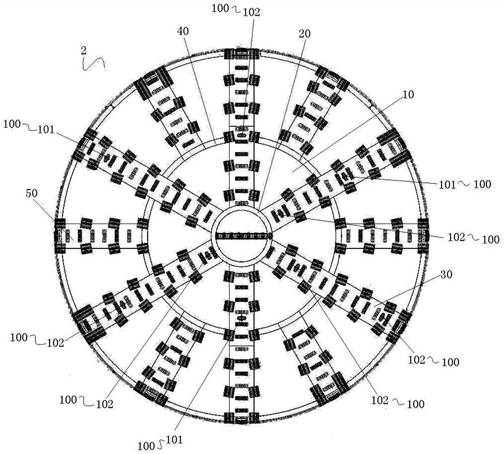
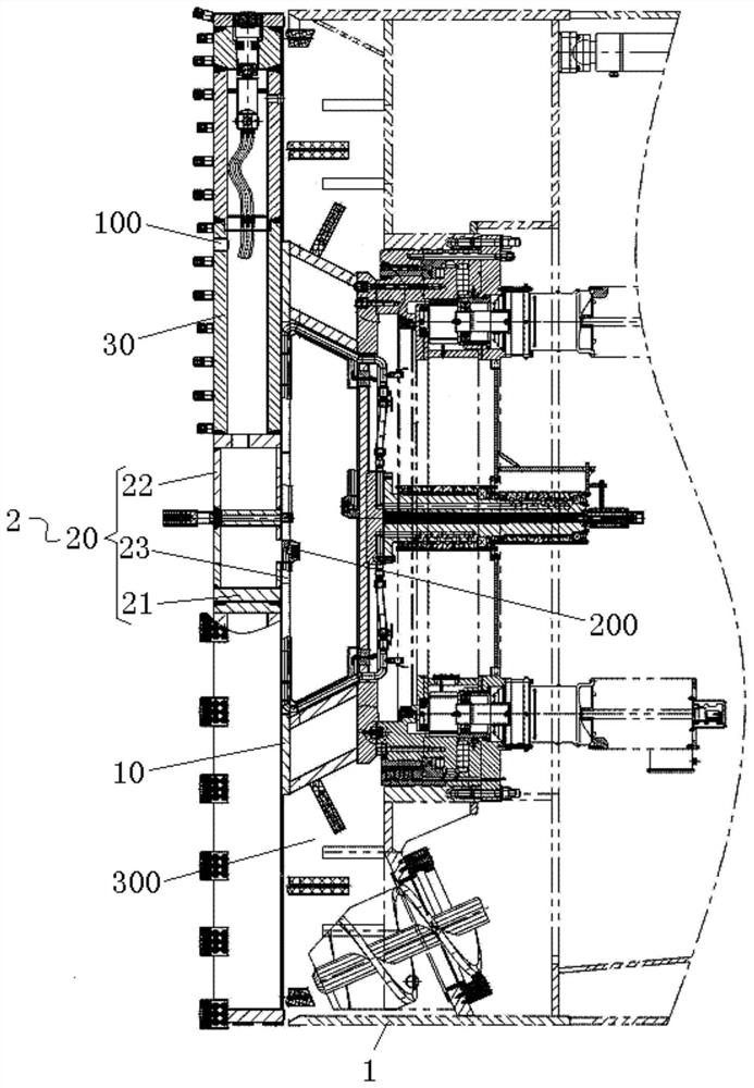
The invention provides a cutter head of a shield machine and a shield machine, wherein the cutter head of the shield machine includes a cutter head body, a central mounting body and long-diameter spokes, and the central mounting body is protrudingly arranged on the cutter head body And located at the center of the cutterhead body; the long-diameter spokes are connected to the central mounting body, and the long-diameter spokes are provided with spray holes, and the spray holes are located on the outer wall of the long-diameter spokes away from the cutterhead body; the shield machine includes a shield Body, cutter head and supply mechanism, the cutter head is rotatably arranged on the shield body; the supply mechanism is arranged on the shield body, and the supply mechanism includes a liquid storage tank, a supply pipeline and a delivery pump. The invention solves the unreasonable setting of the injection holes on the cutter head of the shield machine in the prior art, so that the muck modifier sprayed by the injection holes cannot fully contact the cutting excavation surface, so that the dregs cannot achieve the improvement effect , which in turn causes a large amount of tool wear, which increases the construction cost of the shield tunnel and reduces the construction efficiency of the shield tunnel.

Description

technical field [0001] The invention relates to the technical field of shield tunneling, in particular to a structural improvement of a cutter head of a shield tunneling machine. Background technique [0002] During the construction of subway tunnels, the shield tunneling method is widely used due to its high degree of mechanization, safe construction and good adaptability. [0003] In the prior art, in order to reduce the wear of the soil on the cutting excavation surface to the shield cutter head and the screw machine, the shield cutter head is usually provided with spray holes for spraying the muck modifier to the cutting excavation surface, so as to To improve the muck, however, the existing injection holes are unreasonably set, the cutter head is always in a state of rotation relative to the shield body during cutting, and the muck improver sprayed by the injection holes cannot fully contact the cutting excavation surface, making The slag on the cutting excavation surf...

Claims


Application Information

Patent Timeline
Patent Type & Authority Patents(China)
IPC IPC(8): E21D9/087E21D9/06
CPCE21D9/087E21D9/0678
Inventor 陈健李克金王剑徐传东郭栋王志康耿本涛高洪吉孙伟隋小燕张曦胡少华王北北
Owner 中铁十四局集团隧道工程有限公司
Learn More