
Cement pipe annular end plate separating and positioning system

A technology of ring-shaped end plates and cement pipes, applied in the direction of conveyor objects, transportation and packaging, conveyors, etc., can solve the problems of messy falling, affecting the effect of material distribution, and the difficulty of laying the conveying channel with ring-shaped end plates.

Active Publication Date: 2020-04-24
深圳浩懿贸易有限公司
View PDF8 Cites 0 Cited by
  • Summary
  • Abstract
  • Description
  • Claims
  • Application Information

AI Technical Summary

Problems solved by technology

However, when material distribution is required, the ring-shaped end plate is not easy to lay flat on the conveying channel, and it is easy to fall in a disorderly manner, thereby affecting the material distribution effect

Method used


Image

  • Cement pipe annular end plate separating and positioning system
  • Cement pipe annular end plate separating and positioning system
  • Cement pipe annular end plate separating and positioning system

Examples


Embodiment Construction

[0016] In order to facilitate the understanding of the present invention, the present invention will be described more fully below with reference to the associated drawings. Preferred embodiments of the invention are shown in the accompanying drawings. However, the present invention can be embodied in many different forms and is not limited to the embodiments described herein. On the contrary, the purpose of providing these embodiments is to make the disclosure of the present invention more thorough and comprehensive.

[0017] It should be noted that when an element is referred to as being “fixed” to another element, it can be directly on the other element or there can also be an intervening element. When an element is referred to as being "connected to" another element, it can be directly connected to the other element or intervening elements may also be present. The terms "vertical," "horizontal," "left," "right," and similar expressions are used herein for purposes of ill...


PUM


Abstract

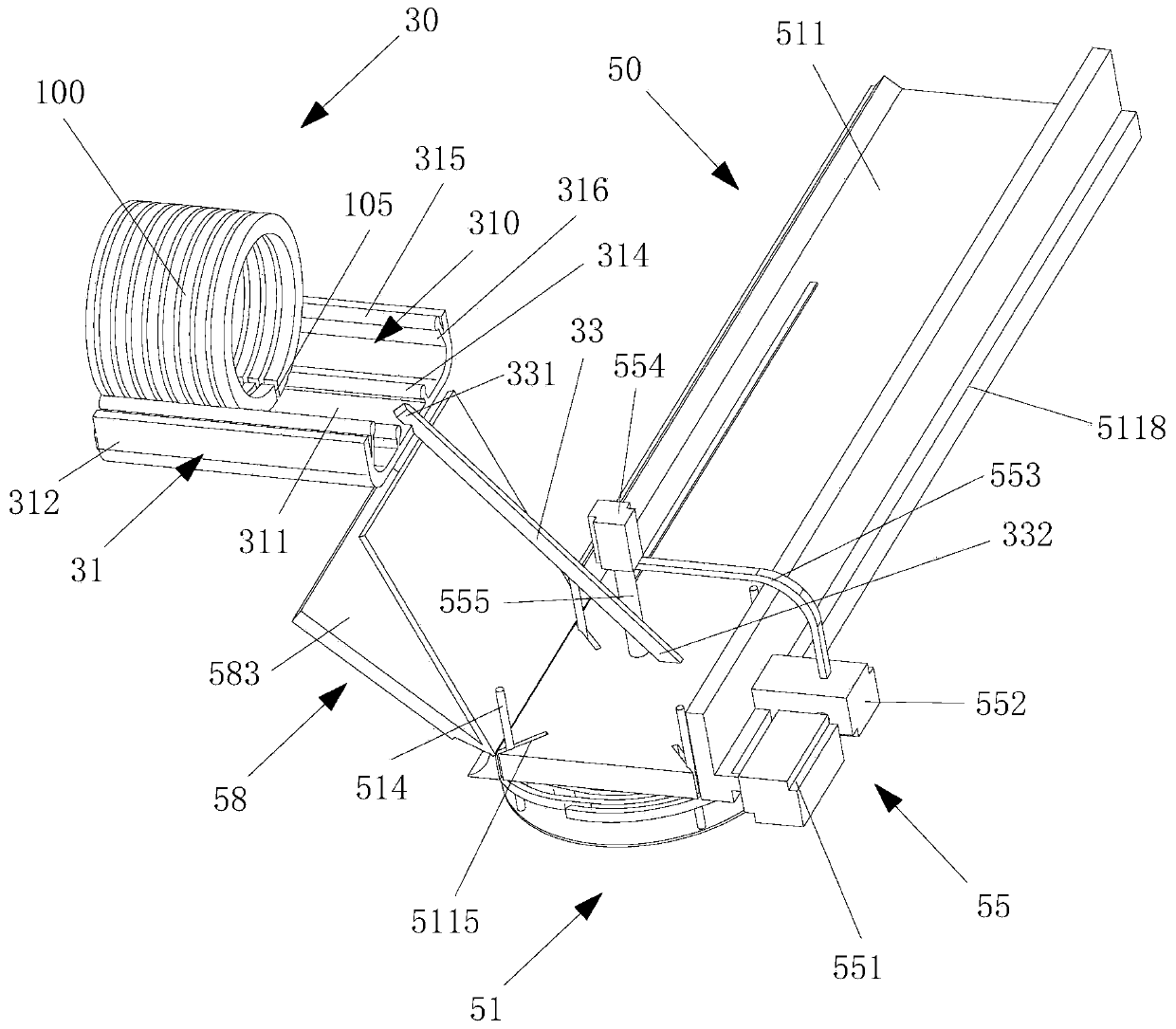
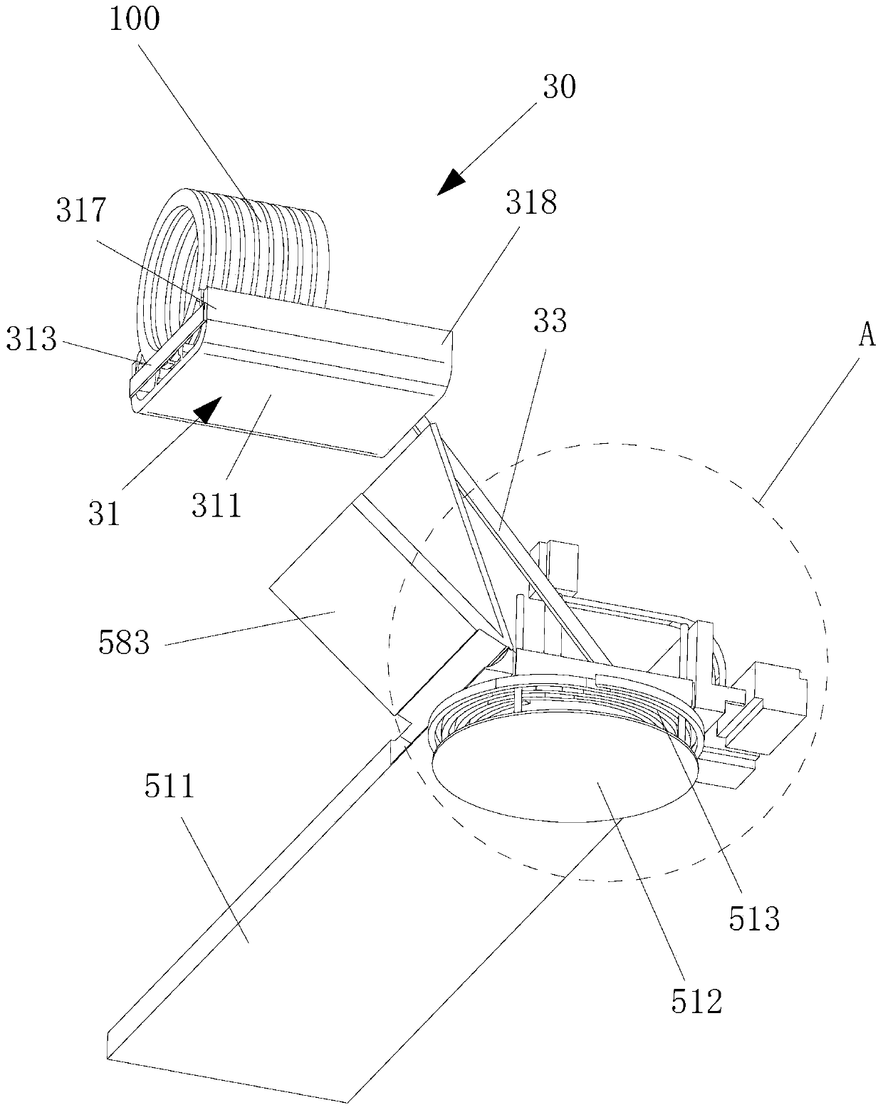
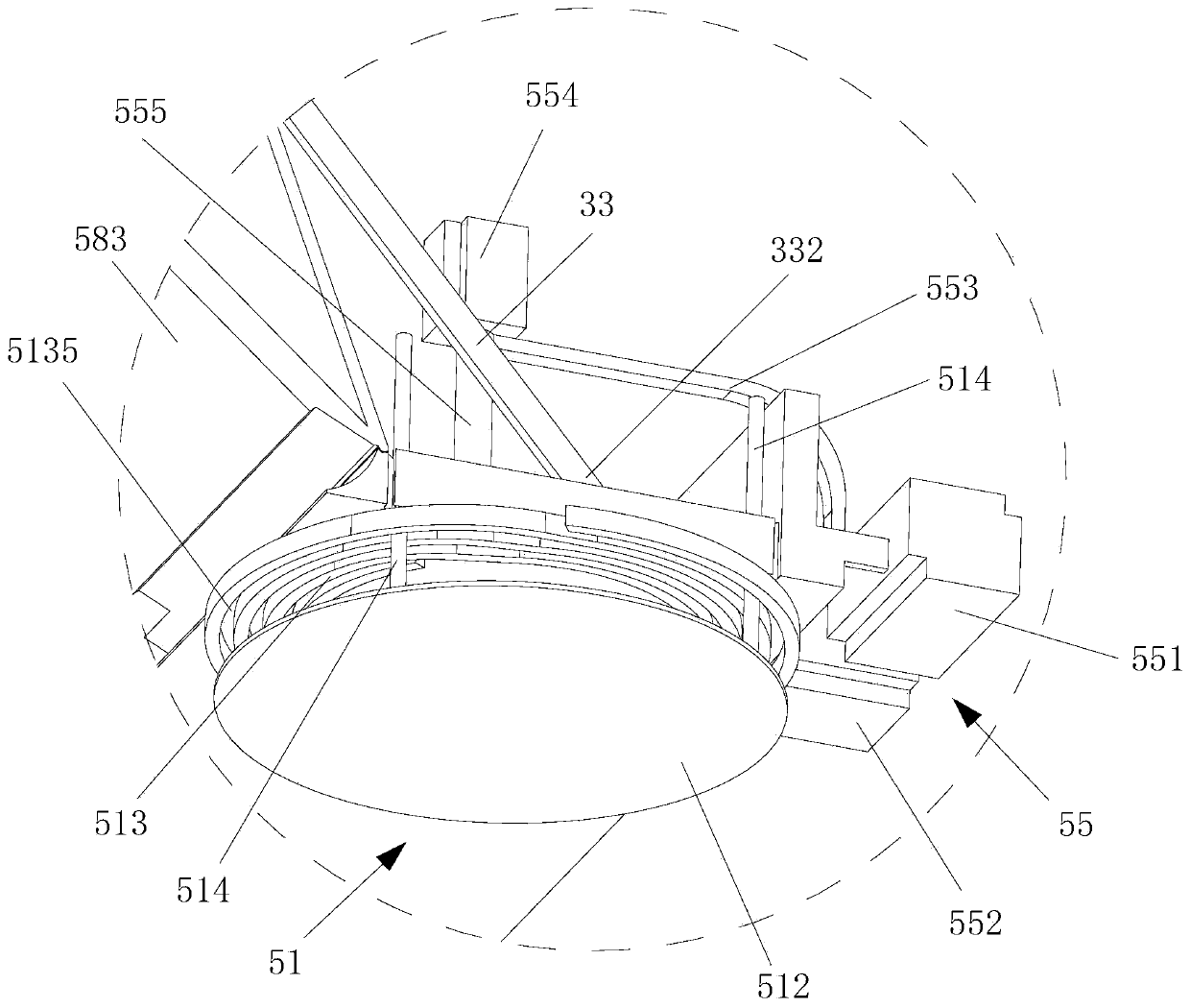
The invention relates to a cement pipe annular end plate separating and positioning system. The cement pipe annular end plate separating and positioning system comprises a material separating mechanism and a positioning mechanism, wherein the material separating mechanism comprises an oblique material separating body, a material pushing power part and a material guiding rod; the oblique material separating body extends upwards; a material separating channel is formed in the oblique material separating body and is used for supporting a plurality of stacked annular end plates; cutting openings of the annular end plates face downwards; the material pushing power part is used for pushing the plurality of annular end plates to fall onto the positioning mechanism in sequence from the oblique material separating body; one end of the material guiding rod is fixed at the end of the material separating channel, and the other end of the material guiding rod extends downwards obliquely to the upper parts of the positioning mechanism. Through the cement pipe annular end plate separating and positioning system, the material separating effect can be improved.

Description

technical field [0001] The invention relates to a material distribution and positioning system for an annular end plate of a cement pipeline. Background technique [0002] In the field of construction, the annular pipe pile end plate is the main part of the prestressed cement pipe. Generally, it is continuously rolled, coiled and spirally formed, and then cut into pieces to form an annular end plate. However, the annular end plate has a slit that passes through the annular end plate and extends in the radial direction of the annular end plate. The cut is produced in a previous process and needs to be welded in a subsequent process. However, when material distribution is required, the ring-shaped end plate is not easy to lay flat on the conveying channel, and it is easy to fall in a disorderly manner, thereby affecting the material distribution effect. Contents of the invention [0003] Based on this, it is necessary to provide a material distribution and positioning syst...

Claims


Application Information

Patent Timeline
IPC IPC(8): B65G47/82B65G47/74B65G47/22
CPCB65G47/22B65G47/74B65G47/82B65G2201/0214
Inventor 霍乐乐
Owner 深圳浩懿贸易有限公司
Learn More