
Lamination machine

A lamination machine and lamination technology, applied in the direction of sustainable manufacturing/processing, climate sustainability, secondary battery manufacturing, etc., can solve the problem of higher quality requirements for machine adjustment personnel, long debugging time, and inconvenient adjustment. and other problems, to achieve the effect of shortening the line change time, saving manpower and costs, and facilitating debugging

Inactive Publication Date: 2014-04-16
SHANDONG ZOUPING HENGXING GRP
View PDF3 Cites 0 Cited by
  • Summary
  • Abstract
  • Description
  • Claims
  • Application Information

AI Technical Summary

Problems solved by technology

[0003] The main disadvantage of the above-mentioned horizontal layout is that it is difficult to adjust the machine, mainly because the gaps between the various mechanisms after the horizontal layout are small, and the mechanism in the middle is inconvenient to adjust the machine due to reasons such as space and length of manpower. Too long will affect the production arrangement, waste manpower, and have high requirements for the quality of the adjustment personnel

Method used

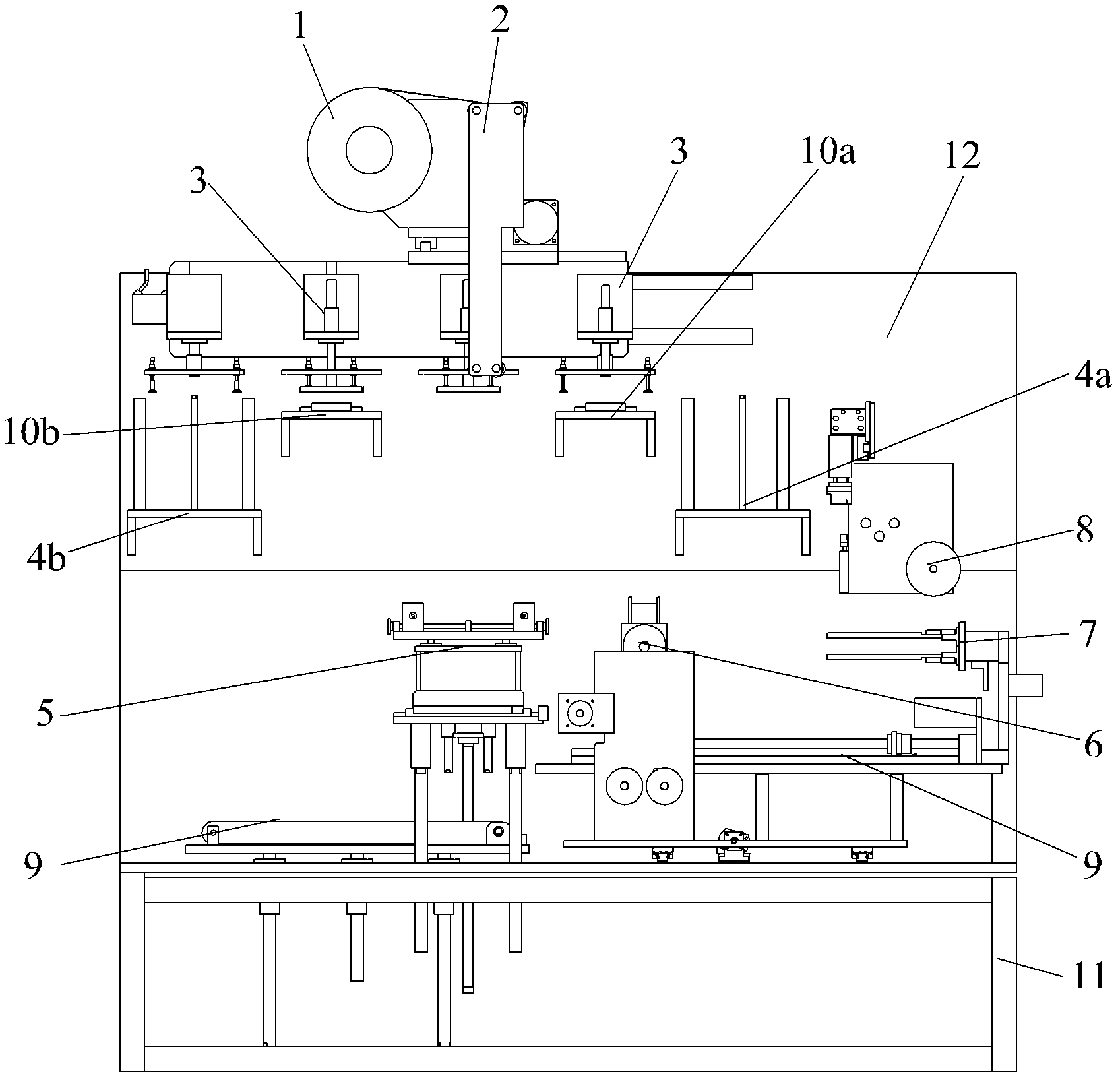
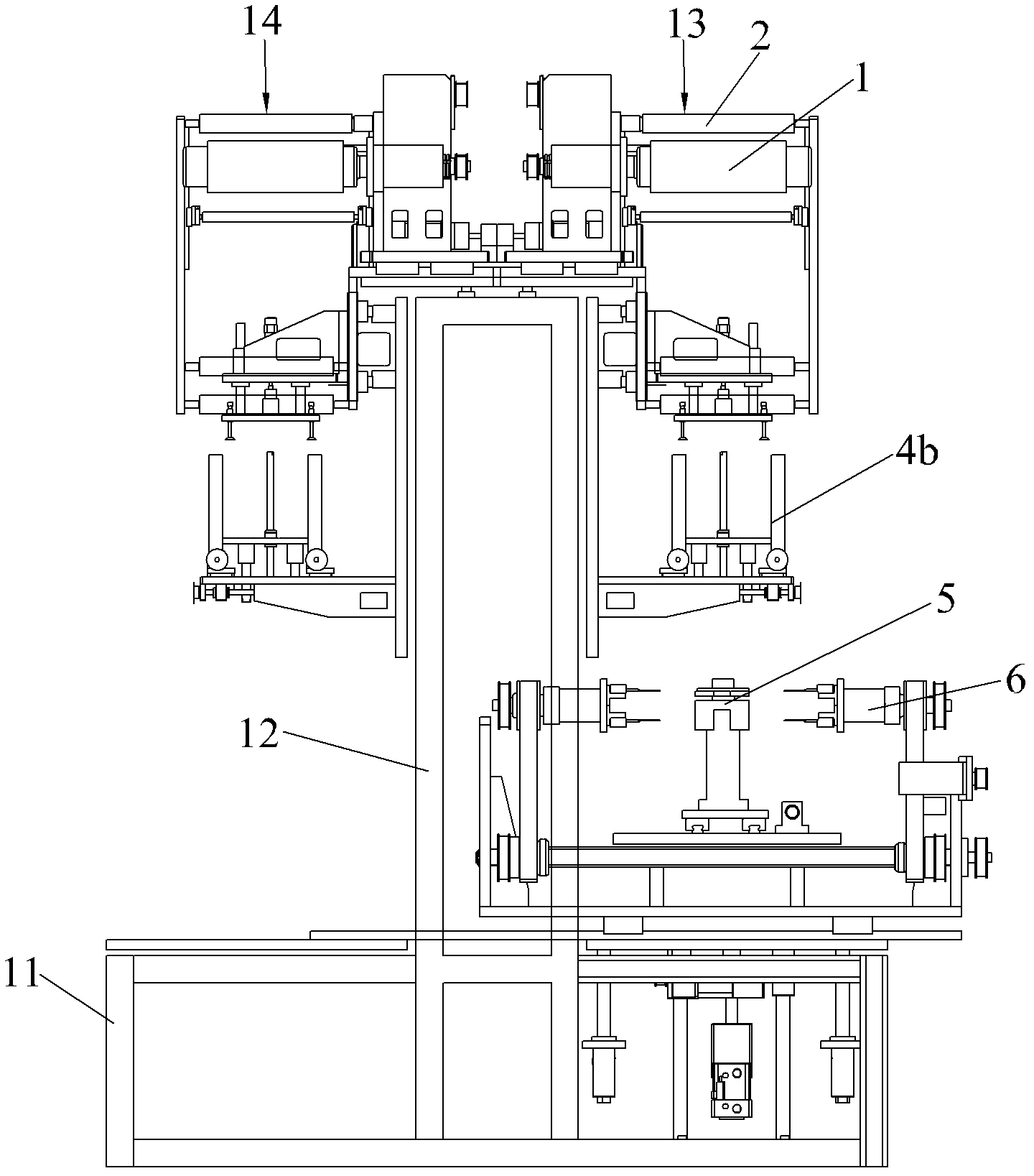
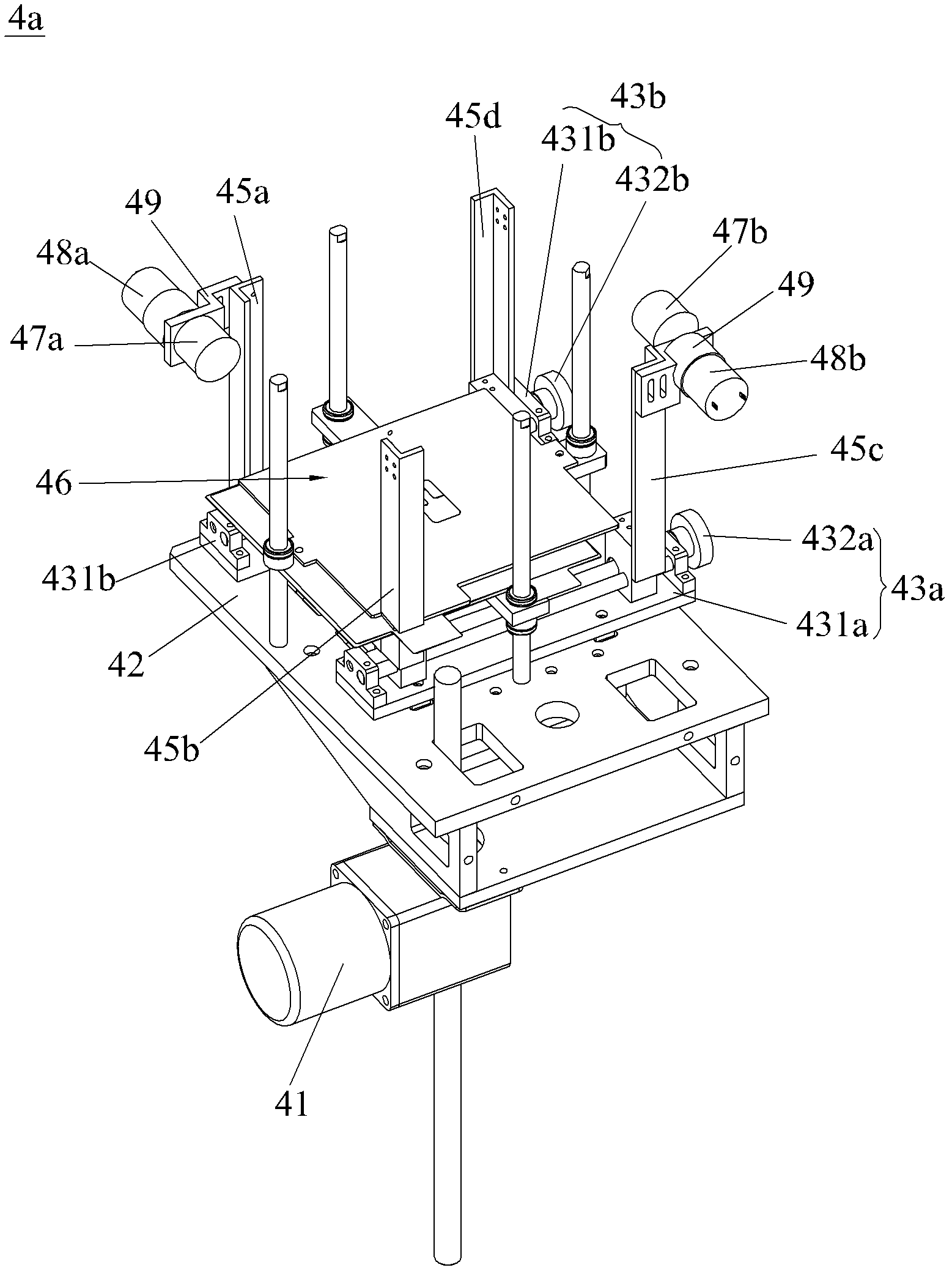

Image

  • Lamination machine
  • Lamination machine
  • Lamination machine

Examples


Embodiment Construction

[0029] Embodiments of the present invention will now be described with reference to the drawings, in which like reference numerals represent like elements.

[0030] Such as figure 1 , figure 2 As shown, the laminate machine of the present invention includes a horizontally placed frame 11, on which a base plate 12 is vertically installed, and between the base plate 12 and the frame 11 is a hollow structure, and the laminate machine includes a first working The mechanism 13 and the second working mechanism 14, specifically, the first working mechanism 13 and the second working mechanism 14 all include a film release mechanism 1, a diaphragm tension edge correction mechanism 2, two feeding mechanisms 3, a positive electrode material box 4a, and a negative electrode material box 4b and stacking mechanism 5; the stacking machine also includes a winding mechanism 6, a material transfer mechanism 7, a glue application mechanism 8 and a discharge pull belt 9, a positive pole positio...


PUM


Abstract

The invention discloses a lamination machine, which comprises a stander and a base plate which are arranged vertically, a first working mechanism, a second working mechanism, a winding mechanism, a material moving mechanism, a rubberizing mechanism and a material discharging pull strip, wherein a hollow structure is formed between the base plate and the stander; the first working mechanism and the second working mechanism are arranged on two sides of the base plate respectively; the winding mechanism is arranged on the stander; the material moving mechanism is connected between the first working mechanism and the second working mechanism in a sliding manner; the rubberizing mechanism is arranged on the base plate and positioned on the same side of the base plate as the winding mechanism; the material discharging pull strip extends to the other end of the stander through the material moving mechanism and the winding mechanism; the horizontal distribution of the first working mechanism and the second working mechanism is changed to be vertical plate distribution; and the first working mechanism and the second working mechanism are arranged on two sides of the vertical base plate. The material moving mechanism is arranged between the first working mechanism and the second working mechanism in the sliding manner and works, so that gaps among the mechanisms are increased; the lamination machine is convenient to debug when a product is mounted or replaced, and the change time is shortened; and the labor and the cost are saved, and the production cost is improved.

Description

technical field [0001] The invention relates to a stacking machine, in particular to a stacking machine which is convenient for debugging, can shorten the time for product line change and save costs. Background technique [0002] The general functional modules of laminating machines currently on the market include material box, positioning mechanism, lamination mechanism, diaphragm unwinding tension edge correction mechanism, material shifting mechanism, winding mechanism and gluing mechanism, etc. The difference is that each mechanism on the equipment There are differences in the layout, but most of them belong to the horizontal layout, that is, all the mechanisms are installed on the horizontal bottom plate. [0003] The main disadvantage of the above-mentioned horizontal layout is that it is difficult to adjust the machine, mainly because the gaps between the various mechanisms after the horizontal layout are small, and the mechanism in the middle is inconvenient to adjus...

Claims


Application Information

Patent Timeline
Patent Type & Authority Patents(China)
IPC IPC(8): H01M10/04
CPCY02E60/12Y02E60/10Y02P70/50
Inventor 张雷
Owner SHANDONG ZOUPING HENGXING GRP
Learn More