Fluorine-based porous membrane and manufacturing method therefor
A porous membrane and fluororesin technology, applied in the field of fluororesin porous membrane, can solve the problems of performance degradation, insufficient air permeability, large size, etc., and achieve the goal of reducing water penetration, reducing porosity, and maintaining internal porosity and air permeability Effect
- Summary
- Abstract
- Description
- Claims
- Application Information
AI Technical Summary
Problems solved by technology
Method used
Image

Examples
Embodiment 1
[0072] [Example 1: Preparation of PTFE porous membrane]
[0073] 100 parts by weight of polytetrafluoroethylene powder (CD145E, AGC) was mixed with 22 parts by weight of a liquid lubricant (trade name: "Isopar H", Exxon Co.) to prepare a single-layer preform.
[0074] Then, the monolayer preform was extruded at a temperature of 50° C. at a rate of 50 mm / minute to produce a sheet with a thickness of about 300 μm. The sheet thus prepared was heated at a temperature of about 200° C. to completely dry the liquid lubricant.
[0075] After the drying step, the preform was uniaxially stretched under the conditions shown in Table 1 below.
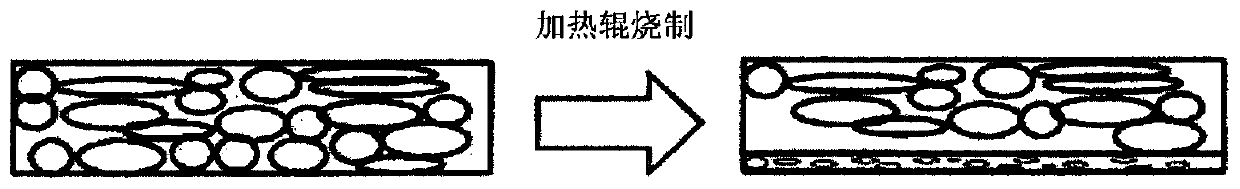
[0076] Subsequently, the stretched preform was fired at a temperature of 360° C. for 10 seconds by using a heating roll to obtain a PTFE porous membrane.
Embodiment 2
[0077] [Example 2: Preparation of PTFE porous membrane]
[0078] 100 parts by weight of polytetrafluoroethylene powder (CD145E, AGC) was mixed with 26 parts by weight of a liquid lubricant (trade name: "Isopar H", Exxon Co.) to prepare a single-layer preform.
[0079] Then, the monolayer preform was extruded at a temperature of 50° C. at a rate of 50 mm / minute to produce a sheet with a thickness of about 300 μm. The sheet thus prepared was heated at a temperature of about 200° C. to completely dry the liquid lubricant.
[0080] After the drying step, the preform was uniaxially stretched under the conditions shown in Table 1 below.
[0081] Subsequently, the stretched preform was fired at a temperature of 360° C. for 10 seconds by using a heating roll to obtain a PTFE porous membrane.
Embodiment 3
[0082] [Example 3: Preparation of PTFE porous membrane]
[0083] 100 parts by weight of polytetrafluoroethylene powder (6J, MDF) was mixed with 22 parts by weight of a liquid lubricant (trade name: "Isopar H", Exxon Co.) to prepare a single-layer preform.
[0084] Then, the monolayer preform was extruded at a temperature of 50° C. at a rate of 50 mm / minute to produce a sheet with a thickness of about 300 μm. The sheet thus prepared was heated at a temperature of about 200° C. to completely dry the liquid lubricant.
[0085] After the drying step, the preforms were uniaxially stretched under the conditions shown in Table 1 below.
[0086] Subsequently, the stretched preform was fired at a temperature of 360° C. for 10 seconds by using a heating roll to obtain a PTFE porous membrane.
PUM
| Property | Measurement | Unit |
|---|---|---|
| thickness | aaaaa | aaaaa |
| thickness | aaaaa | aaaaa |
| pore size | aaaaa | aaaaa |
Abstract
Description
Claims
Application Information
 - R&D
- Intellectual Property
- Life Sciences
- Materials
- Tech Scout
- Unparalleled Data Quality
- Higher Quality Content
- 60% Fewer Hallucinations
Browse by: Latest US Patents, China's latest patents, Technical Efficacy Thesaurus, Application Domain, Technology Topic, Popular Technical Reports.
© 2025 PatSnap. All rights reserved.Legal|Privacy policy|Modern Slavery Act Transparency Statement|Sitemap|About US| Contact US: help@patsnap.com