
Stator winding support

A stator winding and winding support technology is used in the manufacture of motor generators, electrical components, electromechanical devices, etc., which can solve the problems affecting the installation and use of motors, low production efficiency, and only manual operation, and achieve enhanced electrical insulation. performance, increased productivity, reduced damage

Pending Publication Date: 2020-04-21
东莞市富茗自动化科技有限公司
View PDF0 Cites 1 Cited by
  • Summary
  • Abstract
  • Description
  • Claims
  • Application Information

AI Technical Summary

Problems solved by technology

[0002] There are two existing motor stator production processes: with winding bracket and without winding bracket. The former has the following problems: 1. The production cost of multi-position products is high; 2. Changing the original product size affects the installation and use of the motor. The versatility is not strong; 3. The welding efficiency of the enameled wire and the stator lead is low; the latter has the following problems: 1. The creepage distance is difficult to control; 2. It is necessary to wear a sleeve and bind the stator lead to fix the stator lead, so the production efficiency is low and the quality is difficult to control ;In addition, the enameled wire needs to enter the stator through the mold of the winding equipment during the production of these two production processes. During the winding process, the mold of the winding equipment does not protect the stator and the enameled wire in place, and the process after winding can only be operated manually. Low production efficiency and difficult quality control

Method used


Image

  • Stator winding support

Examples


Embodiment Construction

[0020] Below in conjunction with accompanying drawing, the present invention will be described in further detail:

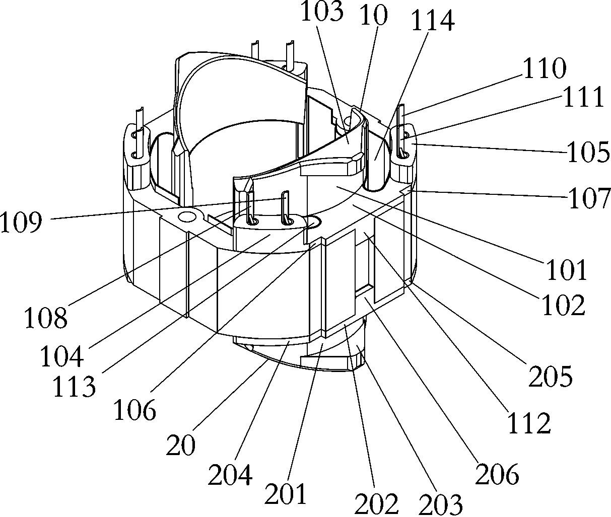
[0021] See figure 1 , a stator winding support of the present invention, comprising two opposite upper winding supports 10 and two opposite lower winding supports 20, the upper winding support 10 includes an upper arc portion 101, an upper horizontal portion 102, the upper limiting part 103 and the upper protrusions 104 and 105, the upper horizontal part 102 is provided in the middle of the outer wall of the upper arc part 101, and the two ends of the upper horizontal part 102 extend along the arc direction with upper extensions respectively. parts 106 and 107, an upper winding space 113 is formed between the upper extension part 106 and the upper arc part 101, and an upper winding space is formed between the upper extension part 107 and the upper arc part 114, the upper extension 106 is provided with the upper protrusion 104, the upper extension 107 is provided...


PUM


Abstract

The invention provides a stator winding support comprising two upper winding supports which are oppositely arranged and two lower winding supports which are oppositely arranged. Each upper winding support comprises an upper arc-shaped part, an upper horizontal part, an upper limiting part and an upper protruding part. The upper horizontal part is arranged in the middle of the outer wall of the upper arc-shaped part, the two ends of the upper horizontal part extend in the arc-shaped direction to form upper extending parts, an upper winding space is formed among the upper extending parts and theupper arc-shaped parts, the upper protruding parts are arranged on the upper extending parts, and two wiring terminals are arranged on the upper protruding parts. The upper limiting parts are arranged above the position between the two upper protruding parts, and the upper limiting parts are arranged on the upper parts of the outer walls of the upper arc-shaped parts; and each lower winding support comprises a lower arc-shaped part, a lower horizontal part and a lower limiting part. The stator winding support has the characteristics of reasonable design, ingenious conception, high productionefficiency, good product quality and the like.

Description

technical field [0001] The invention relates to the technical field of motor stators, in particular to a stator winding support. Background technique [0002] There are two existing motor stator production processes: with winding bracket and without winding bracket. The former has the following problems: 1. The production cost of multi-position products is high; 2. Changing the original product size affects the installation and use of the motor. The versatility is not strong; 3. The welding efficiency of the enameled wire and the stator lead is low; the latter has the following problems: 1. The creepage distance is difficult to control; 2. It is necessary to wear a sleeve and bind the stator lead to fix the stator lead, so the production efficiency is low and the quality is difficult to control ;In addition, the enameled wire needs to enter the stator through the mold of the winding equipment during the production of these two production processes. During the winding process...

Claims


Application Information

Patent Timeline
Patent Type & Authority Applications(China)
IPC IPC(8): H02K15/085
CPCH02K15/085
Inventor 刘至峰陈梦华
Owner 东莞市富茗自动化科技有限公司
Learn More