Mold structure and forming method using same

A model and mold technology, applied in the field of mold structure, can solve problems that affect product appearance, size, aesthetics, etc., and achieve the effect of ensuring integrity

Pending Publication Date: 2019-09-27
HARDA INTELLIGENT TECH CO LTD
View PDF0 Cites 0 Cited by
  • Summary
  • Abstract
  • Description
  • Claims
  • Application Information

AI Technical Summary

Problems solved by technology

However, if the draft angle is too large, it will easily affect the appearance size and aesthetics of the product.

Method used


Image

  • Mold structure and forming method using same
  • Mold structure and forming method using same
  • Mold structure and forming method using same

Examples


Embodiment Construction

[0025] In order to further explain the technical solution of the present invention, the present invention will be described in detail below through specific examples.

[0026] refer to Figure 1 to Figure 9 Shown is a specific embodiment of the present invention.

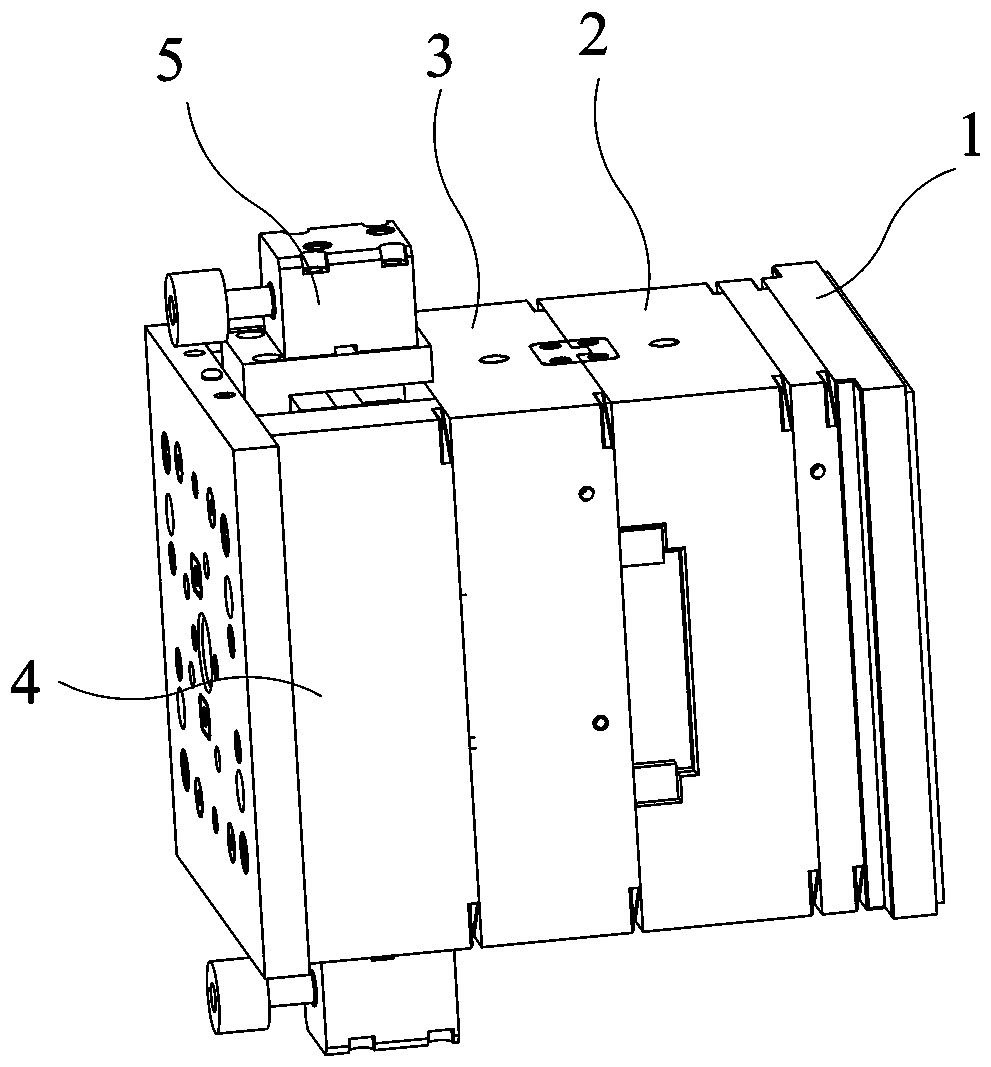
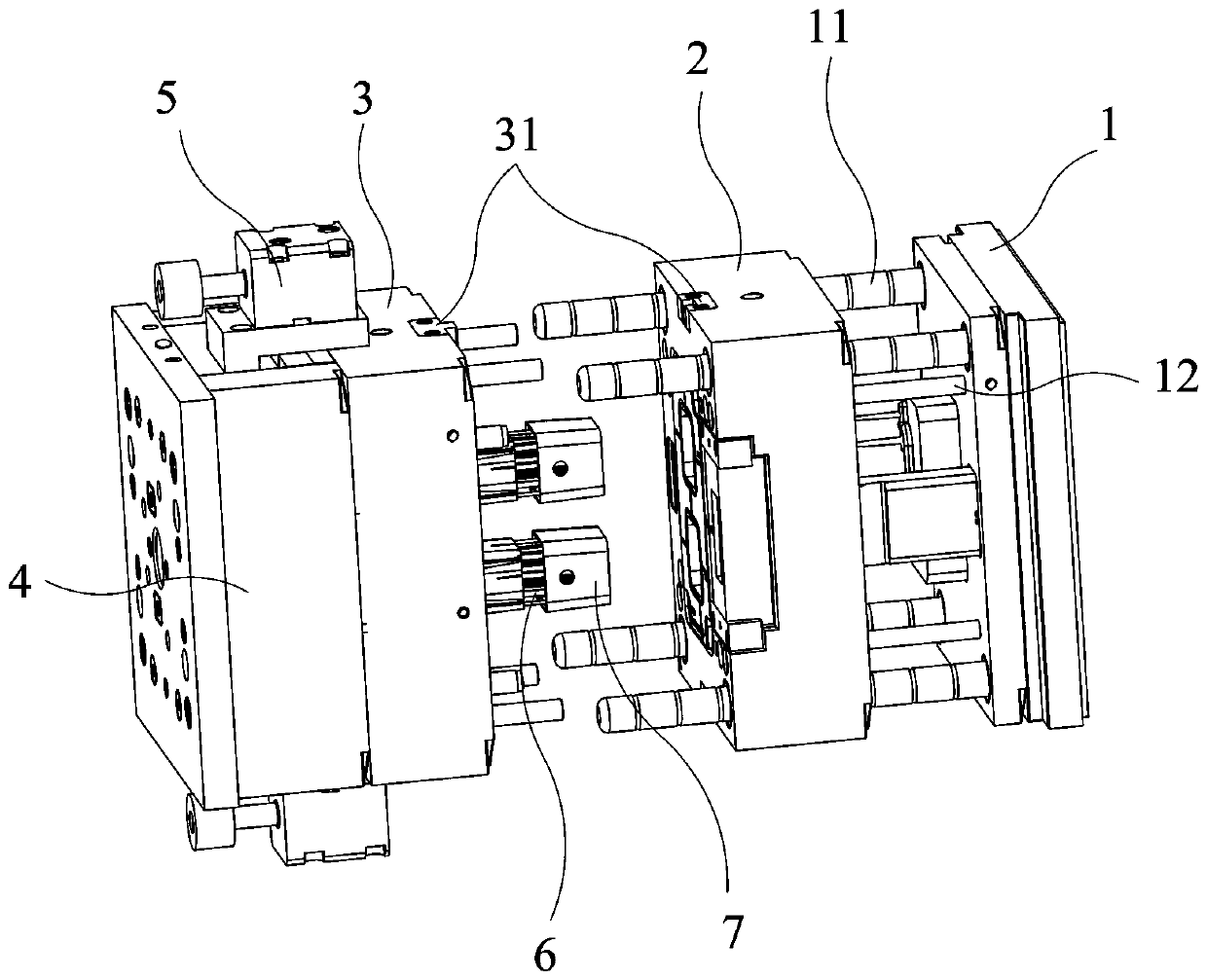
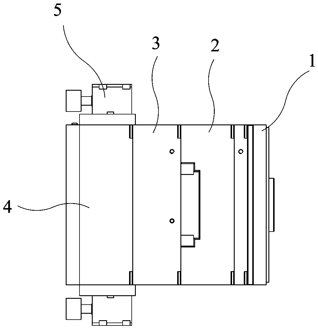
[0027] A mold structure includes a fixed template 1, a fixed mold cavity 2, a movable mold cavity 3, a movable template 4 and an ejection mechanism. The side of the above-mentioned fixed formwork 1 facing the movable formwork 4 is provided with several limit rods 11 , and the fixed mold cavity 2 is slidingly sleeved on the limit rods 11 . A contour screw 12 is arranged between the fixed template 1 and the fixed mold cavity 2, and the contour screw 12 limits the maximum moving distance of the fixed mold cavity 2 relative to the fixed template 1 along the direction of the limit rod 11. The above-mentioned movable model cavity 3 is installed on the movable template 4 and faces the fixed template 1, and the movable te...


PUM


Abstract

The invention discloses a mold structure and a forming method using the same. The mold structure comprises a fixed mold plate, a fixed mold cavity, a movable mold plate, a movable mold cavity and an ejection mechanism; a limit pull rod is arranged on the fixed mold plate; and the fixed mold cavity is slidably connected to the limit pull rod in a sliding mode and is movably matched with the movable mold cavity. A nylon buckle is arranged between the fixed mold cavity and the dynamic mold cavity. An ejection mechanism comprises a driving device and a plurality of telescopic rods, and the telescopic rods are driven by the driving device to be arranged in the movable mold cavity in a penetrating mode. According to the method using the mold structure, the fixed mold cavity is separated from the fixed mold plate by utilizing the three-section displacement and the ejection mechanism of the movable mold cavity, and then products are separated from the movable mold cavity and then is tightly held on the telescopic rods, so that the fixed model cavity is loosened, and the demoulding of the products is realized. According to the mold structure, the demolding can be realized at a small mold pulling inclination, the integrity of the surface lines of the products is ensured, and the appearance size of the products is not influenced.

Description

technical field [0001] The invention relates to the field of molds, in particular to a mold structure and a molding method using the mold structure. Background technique [0002] The draft slope, also known as the demoulding slope, is the slope designed on both sides of the cavity for the convenience of mold release. The orientation of the draft angle depends on the internal and external dimensions of the plastic part. In order to allow the molded product to be ejected out of the mold smoothly, the draft slope must be set on the wall (including the side core and ribs) in the same direction as the mold opening and closing to facilitate demoulding. When the surface of the product is designed with textures, the draft angle needs to be larger, otherwise the textures are easily damaged during the demoulding process. However, if the draft angle is too large, it will easily affect the appearance size and aesthetics of the product. Contents of the invention [0003] The purpose...

Claims


Application Information

Patent Timeline
Patent Type & Authority Applications(China)
IPC IPC(8): B29C33/44
CPCB29C33/44
Inventor 杨永标黄烟
Owner HARDA INTELLIGENT TECH CO LTD
Why Eureka
Try Eureka