Joint Estimation Method of Sensor Amplitude and Phase Error and Target Arrival Angle
An amplitude and phase error and joint estimation technology, which is applied in the field of joint estimation of sensor amplitude and phase error and target arrival angle, can solve the problems of limited estimation accuracy, increase the computational complexity of the algorithm, do not consider sensor errors, etc., and achieve high estimation accuracy and high accuracy. The effect of low computational complexity and high estimation accuracy
- Summary
- Abstract
- Description
- Claims
- Application Information
AI Technical Summary
Problems solved by technology
Method used
Image
Examples
Embodiment 1
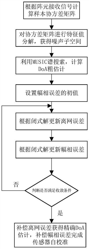
[0056] Embodiment 1: A joint estimation method of sensor amplitude and phase error and target arrival angle in a partial calibration array of the present invention includes the following steps:
[0057] (1) M uniformly arranged omnidirectional receiving antennas form an array, and the spacing d of the array elements is half of the wavelength λ, assuming that the first antenna is used as a reference array element.
[0058] (2) Calculate the sample covariance matrix of the received signal within T snapshots, obtain the noise subspace by decomposing the eigenvalues of the covariance matrix, and then obtain a rough estimate of DoA according to the MUSIC spectrum search method.
[0059] (3) A signal model with both amplitude and phase errors and off-grid errors is established, and a multivariate optimization problem is constructed according to the orthogonality of the signal subspace and the noise subspace.
[0060] (4) The original problem is solved by the method of alternating ...
Embodiment 2
[0097] The estimation of the target arrival angle and the sensor amplitude and phase error of the present invention mainly includes the following steps:
[0098] Step 1: Use the sensor to receive the signal data within T snapshot times, and calculate the corresponding covariance matrix:
[0099]
[0100] where y(t) represents the received signal vector of the array captured by the t-th snapshot.
[0101] Step 2: Perform eigenvalue decomposition on the obtained covariance matrix to obtain the signal subspace And use the orthogonality of the signal subspace and the noise subspace to construct the MUSIC spectral function:
[0102]
[0103] in the formula is the steering vector of the array, and θ is the spatial angle. By dividing the discrete grid θ over the entire space [-90°, 90°] l ∈[θ 1 ,θ 2 ,…,θ L ], search for the K peaks in equation (13) to obtain a rough estimate of the K target angles
[0104] Step 3: Calculate the off-grid error of the k-th target by t...
PUM
 Abstract
Description
Claims
Application Information
 - Generate Ideas
- Intellectual Property
- Life Sciences
- Materials
- Tech Scout
- Unparalleled Data Quality
- Higher Quality Content
- 60% Fewer Hallucinations
Browse by: Latest US Patents, China's latest patents, Technical Efficacy Thesaurus, Application Domain, Technology Topic, Popular Technical Reports.
© 2025 PatSnap. All rights reserved.Legal|Privacy policy|Modern Slavery Act Transparency Statement|Sitemap|About US| Contact US: help@patsnap.com


