Biological laboratory air treatment system

An air treatment system and laboratory technology, applied in the field of air treatment systems, can solve problems such as unfavorable toxic gas discharge and air pollution, and achieve the effects of preventing harmful gas deposition, promoting air circulation, and reducing wind speed

Active Publication Date: 2021-06-25
山东耘威医疗科技有限公司
View PDF14 Cites 0 Cited by
  • Summary
  • Abstract
  • Description
  • Claims
  • Application Information

AI Technical Summary

Problems solved by technology

In order to ensure the air quality of the laboratory, it is unreasonable to increase the exhaust air volume and the number of exhaust outlets, increase the suction volume and the number of suction outlets, and only increase the air volume to solve the problem of air pollution, because Blindly increasing the air volume will cause the airflow in the laboratory to form a vortex area and splash back, causing the toxic gas to spread to other corners of the laboratory, which is not conducive to the discharge of toxic gas

Method used


Image

  • Biological laboratory air treatment system
  • Biological laboratory air treatment system
  • Biological laboratory air treatment system

Examples


Embodiment 1

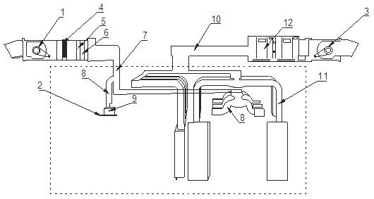
[0030] like Figure 1-5 As shown, this embodiment claims to protect a biological laboratory air treatment system, including a fresh air unit 1, a fresh air pipe group, a fresh air distribution device 2, an exhaust pipe group, an exhaust fan unit 3 and a flow guide device. A surface cooler 4, a primary filter 5 and a medium-efficiency filter 6 are sequentially arranged between the unit 1 and the fresh air pipe group. The fresh air pipe group includes a main fresh air pipe 7 and secondary fresh air pipes 8 at various levels. The end of the fresh air pipe 8 is connected to the fresh air distribution box 9, the end of the fresh air distribution box 9 is connected to the fresh air distribution device 8, and the exhaust pipe group includes the main exhaust pipe 10 and various levels of exhaust pipes. Pipe 11, the exhaust pipe at the end is connected to the flow guide device, and the main exhaust pipe 10 is connected to the exhaust gas treatment device 12 and then connected to the ex...

Embodiment 2

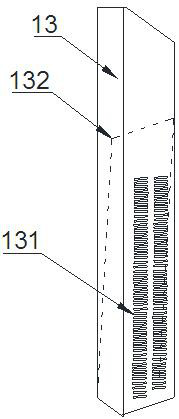
[0038] In this embodiment, the technical features that are the same as those in the above-mentioned embodiment will not be described in detail. The embodiments different from the above in this embodiment are as follows: the vertical flow guide device 13 is in the shape of a cuboid, and the flow guide device faces the side of the laboratory An air outlet is provided, and the air outlet 131 is in the shape of a horizontal strip, and the inside of the vertical deflector 13 is provided with a windshield 132 .

[0039] Preferably: the included angle between the wind deflector 132 and the horizontal direction is 15-45°.

[0040] The surface cooler used in the present invention, primary effect filter, intermediate effect filter are all commercially available products.


PUM


Abstract

The invention discloses an air treatment system for a biological laboratory, which includes a fresh air unit, a fresh air pipe group, a fresh air distribution device, an exhaust pipe group, an exhaust fan unit and a diversion device. The surface cooler, the primary effect filter and the medium effect filter are arranged in sequence. The fresh air pipe group includes the main fresh air pipe and all levels of secondary fresh air pipes. The ends of the secondary fresh air pipes are connected to the fresh air distribution box. , the end of the fresh air distribution box is connected to the fresh air distribution device, the exhaust pipe group includes the main exhaust pipe and the exhaust pipes of each level, the exhaust pipe at the end is connected to the deflector, the main exhaust pipe The air duct is connected to the exhaust gas treatment device and then connected to the exhaust fan unit to discharge the treated exhaust gas. In the biological laboratory air treatment system of the present invention, the airflow runs in one direction without backflow or disorder, and the fresh air distribution device at the air supply port effectively prevents the airflow from blowing directly on the head of the staff.

Description

technical field [0001] The invention relates to an air treatment system, in particular to a biological laboratory air treatment system. Background technique [0002] With the rapid development of pathology, new technologies, new methods and new instruments are widely used in pathological diagnosis and research, which improves the accuracy of case diagnosis and improves the understanding of disease etiology, pathological changes and disease development process. Regularity of research levels. However, the accompanying problems such as exhaust gas and other harmful gas emissions and environmental pollution in the pathology laboratory are also concerned. Strengthening the emission of laboratory exhaust gas is conducive to improving the working environment of the laboratory, avoiding environmental pollution, maintaining public safety and protecting the health of laboratory staff. [0003] In order to solve the problem of air pollution in the biological laboratory and the harm t...

Claims


Application Information

Patent Timeline
Patent Type & Authority Patents(China)
IPC IPC(8): F24F7/007F24F7/003F24F13/02F24F13/08F24F13/30F24F13/28F24F11/74F24F11/89F24F8/10F24F110/66F24F110/30F24F110/40F24F110/50
CPCF24F7/007F24F13/02F24F13/08F24F13/28F24F13/30F24F11/74F24F11/89F24F2110/30F24F2110/40F24F2110/50F24F2110/66F24F8/10
Inventor 王继忠张永刚孙文学
Owner 山东耘威医疗科技有限公司
Why Eureka
Try Eureka